
User's Manual

Integrated L-Band Up/Dn Converter LT3600 CG-1309
Page 14
SECTION 3 Operation
3.0 INTRODUCTION
The Up/Down Converter can be controlled
from the front panel or remotely via a serial
bus located on the rear panel of the converter.
Various menus are available for EDIT and
DISPLAY purposes.
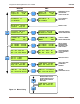
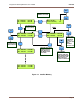
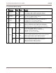
See Figure 3-2 for a listing of the menus.
Section 4 gives a complete description of the
bus commands and conventions for operating
the converter remotely.
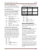
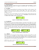
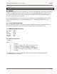
ENT
PRESSING THIS BUTTON
CHANGES THE PARAMETERS
ENTERED WHEN IN ANY OF THE
EDIT MENUS. IF THE
PARAMETERS ARE CHANGED
WITH THE NUMERICAL KEYPAD,
BUT IF THIS BUTTON IS NOT
PRESSED, THE PARAMETER
UNDERLINED WILL NOT CHANGE.
USED FOR ENTERING NUMERICAL
DATA FOR VARIOUS PARAMETER
SETTINGS. THE APPLICABLE
NUMBER IS ENTERED AT THE
CURSER UNDERLINE AND THEN
IS PRESSED TO ACCEPT THE CHANGE.
THE DISPLAY WINDOW SHOWS THE
VARIOUS SETTINGS FOR THE UNIT.
CONTROL AND STATUS MENUS
CAN BE VIEWED BY USING THE UP
AND DOWN MENUS KEYS.
USED TO MAKE FUNCTIONAL
SELECTIONS WHEN IN ANY OF
THE SET MENUS. THESE KEYS
MOVE A CURSER UNDERLINE
LEFT OR RIGHT TO ENTER
NUMERICAL DATA FROM THE
0-9 KEYS.
6
2 4 3 5
LCL
8 9 7 0
ENT
MENU
MENU
UC 1200.000 +25.0 dB
DC 1300.000 +35.0 dB
ALARM
IF RF
UC 1200.000 +25.0 dB
DC 1300.000 +35.0 dB
PRESSING THIS BUTTON
TOGGLES BETWEEN EDIT
AND DISPLAY MODE.
USED TO SCROLL THE
MENU DISPLAY UP
AND DOWN.
1
0
ENT
9
LCL
MENU
MENU
ENT
Figure 3-1 Front Panel Controls and Indicators
Red LED illuminates when any of the monitor
functions in the converter are not within pre-defined
parameters.
PLUGGED; NOT USED
UP/DOWN CONVERTER
LT3600
MONITOR