Steel frame and heavy duty base for greater stability. High quality conveyor belt for longer service life. Parallelism between the sanding drums and the conveyor belt is adjusted by convenient adjustment screw. Large hand wheel adjusts conveyor table height. Magnetic safety switch. Two (2) 4” dust outlets. Graduated depth scale in both inches and metric to indicate sanding thickness. Conveyor belt equipped with a safety switch with removable key. Dual v-belt driven sanding drums.
GENERAL® INTERNATIONAL 8360 Champ-d’Eau, Montreal (Quebec) Canada H1P 1Y3 Telephone (514) 326-1161 • Fax (514) 326-5555 www.general.ca THANK YOU for choosing this General® International model 15-250 M1 24” Horizontal Double Drum Sander. This machine has been carefully tested and inspected before shipment and if properly used and maintained, will provide you with years of reliable service.
Rules for Safe Operation To help ensure safe operation, please take a moment to learn the machine’s applications and limitations, as well as potential hazards. General® International disclaims any real or implied warranty and hold itself harmless for any injury that may result from the improper use of it’s equipment. 1. Do not operate the sander when tired, distracted, or under the effects of drugs, alcohol or any medication that impairs reflexes or alertness. 2.
ELECTRICAL REQUIREMENTS Before connecting the machine to the power source, verify that the voltage of your power supply corresponds with the voltage specified on the I.D. nameplate located on the back of the machine. A power source with greater voltage than needed can result in serious injury to the user as well as damage to the machine. If in doubt, contact a qualified electrician before connecting to the power source. This tool is for indoor use only. Do not expose to rain or use in wet or damp locations.
24” HORIZONTAL DOUBLE DRUM SANDER 15-250 M1 IDENTIFICATION OF MAIN PARTS AND COMPONENTS CRANK HANDLE DUST OUTLETS CONVEYOR MOTOR START/STOP SWITCH WITH SAFETY KEY CONVEYOR BELT SPEED ADJUSTING KNOB SANDING DRUM MOTOR MAGNETIC POWER SWITCH CONVEYOR BELT DEPTH GAUGE CONVEYOR TABLE 5
UNPACKING Carefully unpack and remove the unit and its components from its shipping container and check for missing or damaged items as per the list of contents below. NOTE: Please report any damaged or missing items to your GENERAL® INTERNATIONAL distributor immediately. LIST OF CONTENTS Once the parts have been removed from the packaing, you should have the following items: QTY 24” HORIZONTAL DOUBLE DRUM SANDER . . . . . . . . .1 HARDWARE BAG (from left to right) — — — — — — HANDLE KNOB . . . . . . . .
PLACEMENT WITHIN THE SHOP / ESTABLISHING A SAFETY ZONE This sander is heavy. Do not over-exert. The help of an assistant will be needed for the following step. To limit the risk of serious injury or damage to the machine, any equipment used to lift this machine (forklift or lifting hook) should have a rated capacity in excess of 570 lbs (259 kg).
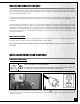
INSTALL THE CONTROL BOX 1 2 1. Loosen, but do not remove, the 2 hex bolts, , installed on the top right hand corner of the machine. 2. Slide the control box onto the heads of the bolts. 3. Tighten the bolts to secure the control box in place, with a 10 mm open end wrench, . Do not plug in the power cord yet. CONNECTING TO A DUST COLLECTOR Do not operate this sander without an adequate dust collection system properly installed and running.
BASIC FUNCTIONS OF THE UNIT This 24” horizontal double drum sander is designed for surface sanding of wooden cabinet doors, flat wooden panels, wide glue-ups and other natural wood products only. This sander is not intended (and should not be used) to sand any material other than wood. The main time saving feature of this unit is that it allows for sanding at 2 successive grits in one single pass.
ON/OFF POWER SWITCHES This sander is equipped with 2 different ON/OFF power switches: one magnetic switch for the drums motor and one switch with a safety key for the conveyor motor. DRUM MOTOR MAGNETIC SWITCH This model 15-250 M1 drum sander is equiped with a MAGNETIC SAFETY SWITCH , . located on the control box, designed to protect the unit and the user from power surges, power outages and unwanted or unintentional start-up.
SWITCHES OFF 1. Set both of the power switches on the sander to the off position, , and disconnect the machine from the power source, . Note: If the sander is permanently connected to a circuit (hard-wired), set the wall panel circuit breaker or main circuit interrupter to the off position. 2. Unscrew the 2 screws, box front cover. , and remove the control 4. Reinstall and rescrew the control box cover. 5. Reconnect the sander to the power source. 6.
CHANGING FEED SPEED The conveyor speed ranges from 3 to 20 FPM (Feet Per minute). Decrease speed Increase speed The feed speed adjustment knob, , is located on the control box, on the right hand side of the machine. - Turn the knob clockwise, , to increase the feed rate. - Turn the knob counter-clockwise, the feed rate.
Always make sure the sander is disconnected from the power source before opening the drum cover and removing/installing sanding belts or adjusting the height of the rear drum. 3. To access the sanding belts, unlock the drum cover latch, , and open the top cover. The sanding belts are tightly wound around the drums and attached at both ends by spring loaded clamps, . (Fig. 5) 4. Remove the sanding belt from the rear drum. (See section “Removing the sanding belts” on page 17). 5.
OPERATING INSTRUCTIONS CHECKLIST BEFORE STARTING Make sure to have on safety glasses as well as hearing and respiratory protection at all times when using the sander. Make sure you and any assistants are wearing safe appropriate workshop attire. Roll up long sleeves, secure long hair and remove any jewelry: watches, rings, bracelets or anything that could become caught in the conveyor feed rollers or the drums, potentially causing serious injury. • Make sure a dust collector is properly attached.
OPERATIONS STEP-BY-STEP To reduce the risk of damage to the sander or the workpiece, as well as a potential for personal injury, after initial set-up as well as before each use, make sure that everything is securely installed and that all fasteners and moving parts on this sander are locked in place before starting the machine. 1. Set the height of the rear drum (see section: “Adjusting the height of the rear drum” on page 12.) 2. Place the workpiece on the conveyor belt. 3.
LUBRICATION Disconnect machine from power source, before performing any maintenance or lubrication. Note: Unscrew and remove both left and right cover to access the conveyor elevation mechanism. Fig. 8 Keep threaded rods, , and gears, , located at either end of the machine greased and free of dust or debris. Clean and remove dust, debris, and old grease after every 10-15 hours of use. After cleaning, re-apply a generous coating of any common automotive bearing grease. (Fig. 8) PERIODIC MAINTENANCE 1.
You can also purchase them from your local tool, abrasives or sharpening supply dealer. You can find these products in most areas. However, we recommend that you choose higher quality brand name belts. If the sanding paper is too thick or too thin, or of inconsistent quality, it may not be properly gripped by the two-step clamps. Tip: Cleaning the sand paper with a belt dresser will extend the life of the sand paper. Consult your local distributor.
MOUNTING A NEW SANDING BELT Note: To extend belt life and avoid premature breakage, take note of the direction of the arrows printed on the inside of the sanding belt to make sure you install the belt in the correct direction. 1. Pull and hold the left spring loaded clamp. DO 3. 18 2. Insert the left tab of the sanding belt in the slot, pushing all the way in (as far as possible), then release the clamp to lock the tab in place.
Note: The spring loaded clamp at the right end of the drums is a two stage spring. The first stage grabs the paper and the second stage pulls the clamp backward inside the drum, providing proper tension to the sanding belt. FIRST STAGE 4. Push and hold the right two-step clamp forward with your thumb. SECOND STAGE 5. Insert the right tab of the sanding belt in the slot, pushing all the way in (as far as possible), until it is tight, .
3/4” Max. 3/4” Note: With the sanding belt tab, , properly inserted in the clamp, the clamp assembly, ,should not pull back more than 3/4", , from the slot in the drum, . If the clamp assembly pulls back further than 3/4" the sanding belt tab needs to be inserted further into the clamp to remove some of the slack in the belt. Otherwise the paper will not be properly tensioned on the drum and the belt may loosen, unwind, or possibly tear when it comes in contact with the workpiece. 8.
5. Remove the belts from the upper pulleys, install new belts. (Fig. 11) , and 6. Lift the motor and install the other end of the belts in the slot on the lower pulleys. 7. Put the motor back to its initial position, then retighten the lock and lock nut located on the motor positioning plate. Fig. 11 REPLACING MOTOR BEHIND Never attempt to repair motor yourself. Contact a qualified technician.
Note: Generally, snipe problems occur when pressure rollers are set too low. Less frequently, this problem occurs as a result of too much tension in the pressure rollers. It is thus possible that, although you adjusted the height of the rollers, you still get snipe on your board. If this is the case, adjust the tension of the rollers. Proceed as follows: Always turn off and unplug the sander before performing any maintenance or adjustments. 1.
RECOMMENDED OPTIONAL ACCESSORIES FOR YOUR SANDER We offer a large variety of products to help you increase productivity, accuracy and safety when using your sander. Here’s a small sampling of accessories available from your local General International dealer. For a complete list, visit our website at www.general.ca.
25 42 13 4 47 43 23 6 7 16 47 34 16 42 4 13 24 20 21 68 43 35 36 28 22 28 41 23 18 16 5 4 41 13 24 27 16 8 35 16 9 4 13 28 14 0 68 26 13 17 47 43 2 13 2 11 27 8 23 15 13 14 42 42 11 39 15 27 13 17 0 14 28 27 43 8 16 32 42 9 7 8 10 6 2 13 7 47 28 42 27 4 7 28 6 10 12 37 38 38 13 1a 13 9 2 2 13 85 5 1 33 13 1 3 4 2 43 13 47 1 2 13 3 13 42 1 5 43 85 47 42 3 4 14 4 2 13 2 28 3 40 13 27 12 14 17
6 13 12 3 2 10 10 5 7 19 10 3 4 12 4 12 12 4 28 47 1 10 27 93 43 6 10 0 13 65 44 65 12 3 10 3 7 10 10 2 10 9 60 47 1 4 08 43 7 12 2 11 10 0 2 12 10 4 4 4 47 3 10 9 3 12 3 8B 12 11 0 10 7 11 14 7 19 2 10 3 11 1 11 0 10 2 10 7 10 1 11 28 3 12 3 1 10 12 4 13 0
93 27 92 93 93 27 27 93 42 42 94 95 43 97 43 27 47 47 93 44 90 27 95 43 93 26 81 27 93 27 27 44 43 93 55 99 54 51 54 55 55 55 49 55 55 1 16 61 55 50 5 14 0 1 2 3 4 5 6 7 8 9 10 11 12 13 42 27 1 0 2 4 3 5 98 42 47 43 43 7 4 61 61 55 59 61 43 72 73 3 19 81 26 48 14 5 81 26 83 62 87 56 22 28 71 26 70 66 57 58 53 22 52 69 86 5 8a 59 26 27 81 26 81 88 2 2 27 26 63 56 81 64 26 81 81 26 80 22 22 85 81 82 93 88 7 8
1 28 9 12 4 16 2 16 28 27 26 27 28 26 27 81 26 27 81 8 12 26 9 12 27 81 28 27 3 16 8 12 9 12 26 27 28 26 27 81 26 8 12 27 9 12 81 26 27 81 2 16
PARTS LIST - 15-250 M1 28 PART N0. REF N0.
PARTS LIST - 15-250 M1 PART N0. REF N0.
PARTS LIST - 15-250 M1 30 PART N0. REF N0.
PARTS LIST - 15-250 M1 PART N0. REF N0.
15-250 M1 8360, Champ-d’Eau, Montreal (Quebec) Canada H1P 1Y3 Tel.: (514) 326-1161 Fax : (514) 326-5565 Parts & Service Fax : (514) 326-5555 Order Desk orderdesk@general.ca www.general.ca IMPORTANT: When ordering replacement parts, always give the model number, serial number of the machine and part number. Also a brief description of each item and quantity desired.