VARIABLE SPEED “MAXI-LATHE VF” 25-114QC IDENTIFICATION OF MAIN PARTS AND COMPONENTS A B T S Q C L G H N M R O U D I J K P F E V W X Z Y ABCDEFGHIJKLM- HEADSTOCK FACE PLATE SPUR CENTER MOTOR PIVOT HANDLE MOTOR PIVOT LOCKING LEVER MOTOR FLYWHEEL LEFT CARRYING HANDLE ON/OFF SWITCH SPINDLE SPEED CONTROLLER THERMAL RELAY RE-SET (under the switch) TOOL REST TOOL REST CARRIAGE NOPQRSTUVWXYZ- TOOL REST LOCKING LEVER TOOL REST CARRIAGE LEVER LATHE BED LIVE CENTER TAILSTOCK LOCKING LEVER TAILSTOCK
BASIC FUNCTIONS This General International model 25-114QC M1 Maxi-Lathe VF is designed specifically for small to medium hobby type wood turning projects. With a maximum swing over bed of 14”, a distance between centers of 17”, and 3 electronically controlled variable speed ranges (250-800, 550-1700 and 1200-3600), the 25-114QC is ideal for small turnings such as pens, as well as bowls and small to medium spindles.
CLEAN UP The unpainted cast-iron surface of the lathe bed is covered with a protective coating that helps prevent rust from forming during shipping and storage. Remove this protective coating by rubbing with a rag dipped in kerosene, mineral spirits or paint thinner. (Handle and dispose of potentially flammable solvent soaked rags according to manufacturers’ safety recommendations.
ATTACH THE CORD STORAGE HOOKS CONNECT THE CONTROL BOX TO THE MOTOR A C B Attach the two cord storage hooks A to the rear of the lathe using the Phillips head screws already mounted on the lathe, as shown B. Note: Two plastic clips are mounted on the rear of the lathe for convenient knock out bar storage C. MAKE SURE THAT THE LATHE IS NOT CONNECTED TO A POWER SOURCE.
BASIC ADJUSTMENTS & CONTROLS CONNECTING TO A POWER SOURCE TO REDUCE THE RISK OF SHOCK OR FIRE DO NOT OPERATE THE UNIT WITH A DAMAGED POWER CORD OR PLUG. REPLACE DAMAGED CORD OR PLUG IMMEDIATELY. SWITCH OFF TO AVOID UNEXPECTED OR UNINTENTIONAL START-UP, MAKE SURE THAT THE POWER SWITCH IS IN THE OFF POSITION BEFORE CONNECTING TO A POWER SOURCE. Once the assembly steps have been completed and the unit is safely secured to a work surface, plug the power cord into an appropriate outlet.
SPINDLE SPEED CONTROL 3 SPEED RANGES The spindle speed ranges from 250 to 800, 550 to 1700 and from 1200 to 3600 Revolutions Per Minute (RPM), depending on the positionning of the drive belt on the pulleys. High: 1200-3600 RPM Medium: 550-1700 RPM Low: 250 to 800 RPM Note: Refer to the Speed Recommendations chart below for speed selection. Changing between the 3 speed ranges requires moving the drive belt from one set of drive pulleys to another (H, M or L). The speed range will vary.
TOOL REST CARRIAGE & TOOL REST ADJUSTMENTS B A The tool rest carriage can be moved along the bed slide ways as needed. Loosen the tool rest carriage lever A and move the carriage to the desired location. Re-tighten the lever securely after adjustment. The tool rest should be adjusted so that its top is 1/8" above the center of the workpiece. Loosen the tool rest locking lever B and adjust the height and position of the tool rest as needed. Re-tighten the lever securely after adjustment.
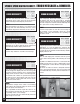
MOUNTING & REMOVING THE TAILSTOCK LIVE CENTER TAILSTOCK REAR VIEW H J I K The tailstock has an MT#2 taper hole into which the live center fits. 1. Make sure the shank of the live center and the tailstock hole are clean and free of debris and fit the live center firmly in the spindle hole by hand H.
MOUNTING A WORKPIECE TO THE FACE PLATE For turning applications where the workpiece cannot be secured between the headstock and tailstock centers (such as bowl turning) the face plate must be used to secure the workpiece to the headstock spindle. 1.
SPINDLE SPEED DIGITAL READOUT - ERROR MESSAGES & REMEDIES ERROR MESSAGE E1 When the onboard heat sensor detects a running temperature above 185°F (85°C) the motor will shut off automatically and the display will show “E1”. REMEDY Allow the machine some time to cool off. An E1 error message will clear automatically when the sensor temperature drops back down below 176°F (80° C).
ERROR MESSAGE E7 If (A) the white wire of the control box is not properly connected with the white wire of the motor (page 10 “Connect the control box to the motor”), or if (B) the motor sensor is disconnected or somehow damaged, the machine will either not run, or run for only a few seconds and then shut off and the display will show “E7”.