SETUP & OPERATION MANUAL FEATURES 7” MOLDER Cast-iron table and head for smooth vibration free performance. Heavy-duty cast-iron dovetailed column, precision machined for smooth cutter head height adjustment. Precision high-speed, sealed, pre-lubricated bearings. Independent, variable speed feed motor provides added control for precision, tearout free performance with hardwoods and stock with figured grain. Jackscrew style cutter head adjustment system.
GENERAL® INTERNATIONAL 8360 Champ-d’Eau, Montreal (Quebec) Canada H1P 1Y3 Telephone (514) 326-1161 • Fax (514) 326-5555 • www.general.ca THANK YOU for choosing this General® International model 30-120 M1 7” Molder. This molder has been carefully tested and inspected before shipment and if properly used and maintained, will provide you with years of reliable service.
GENERAL® & GENERAL® INTERNATIONAL WARRANTY All component parts of General®, General® International and Excalibur by General International ® products are carefully inspected during all stages of production and each unit is thoroughly inspected upon completion of assembly.
TABLE OF CONTENTS Rules for safe operation . . . . . . . . . . . . . . .5 Electrical requirements . . . . . . . . . . . . . . .6 Grounding instructions . . . . . . . . . . . . . . . . . . . . . . .6 Circuit capacity . . . . . . . . . . . . . . . . . . . . . . . . . . . . .6 Extension cords . . . . . . . . . . . . . . . . . . . . . . . . . . . . .6 Identification of main parts and components . . . . . . . . . . . . . . . . . . . .
RULES FOR SAFE OPERATION To help ensure safe operation, please take a moment to learn the machine’s applications and limitations, as well as potential hazards. General® International disclaims any real or implied warranty and holds itself harmless for any injury that may result from improper use of its equipment. 1. Do not operate this molder when tired, distracted, or under the effects of drugs, alcohol or any medication that impairs reflexes or alertness. 13.
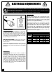
ELECTRICAL REQUIREMENTS BEFORE CONNECTING THE MACHINE TO THE POWER SOURCE, VERIFY THAT THE VOLTAGE OF YOUR POWER SUPPLY CORRESPONDS WITH THE VOLTAGE SPECIFIED ON THE MOTOR I.D. NAMEPLATE. A POWER SOURCE WITH GREATER VOLTAGE THAN NEEDED CAN RESULT IN SERIOUS INJURY TO THE USER AS WELL AS DAMAGE TO THE MACHINE. IF IN DOUBT, CONTACT A QUALIFIED ELECTRICIAN BEFORE CONNECTING TO THE POWER SOURCE. THIS TOOL IS FOR INDOOR USE ONLY. DO NOT EXPOSE TO RAIN OR USE IN WET OR DAMP LOCATIONS.
” MOLDER 30-120 M1 IDENTIFICATION OF MAIN PARTS AND COMPONENTS A C B D F G G E E I H J M k L N O A- CUTTER HEAD HEIGHT ADJUSTMENT HANDWHEEL H- FEED SPEED CONTROL KNOB B- BELT COVER J- THERMAL RELAY C- DUST HOOD K- DRIVE MOTOR D- FEED MOTOR L- MAGNETIC SWITCH WITH LOCK-OUT KEY E- TABLE EXTENSION ROLLERS M- DRIVE MOTOR COVER PANEL F- FENCES N- STAND G- FENCE LOCK KNOBS O- LEVELING FOOT I- FEED MOTOR SWITH WITH SAFETY KEY 7
UNPACKING Carefully unpack and remove the molder and its components from the box and check for damaged or missing items as per the list of contents below. NOTE: Please report any damaged or missing items to your General International distributor immediately. LIST OF CONTENTS A QTY A- MOLDER .........................................................................1 B- HANDWHEEL ..................................................................1 LEVELING FOOT & HARDWARE: C - HEX NUT .....................
PLACEMENT WITHIN THE SHOP / ESTABLISHING A SAFETY ZONE THIS MODEL 30-120 M1 7” MOLDER IS HEAVY. DO NOT OVER-EXERT. THE HELP OF AT LEAST ONE ASSISTANT OR A HOIST WILL BE NEEDED FOR THE FOLLOWING STEP. TO LIMIT THE RISK OF SERIOUS INJURY OR DAMAGE TO THE MACHINE, ANY EQUIPMENT USED TO LIFT THIS MACHINE SHOULD HAVE A RATED CAPACITY IN EXCESS OF 242 LBS (110 KG).
CLEAN UP The protective coating on the table, K, prevents rust from forming during shipping and storage. Remove it by rubbing with a rag dipped in kerosene, mineral spirits or paint thinner. K Important: Dispose of potentially flammable solventsoaked rags according to manfacturer’s safety recommendations. A putty knife, held flat to avoid scratching the surface, may also be used to scrape off the coating followed by clean-up with solvent.
H F F I G I I I F 2. Using the supplied 4 mm T-handle wrench, loosen and remove the 3 Allen screws F, then remove the upper pulley cover G. 3. Using the supplied 4 mm T-handle wrench, unscrew and remove the 4 button head screws I that secure the motor cover panel to the stand. Note: The drive belt is already installed on the upper pulley H . J K 4. Remove the motor cover panel to access the motor J. 5.
CONNECTING TO A POWER SOURCE TO REDUCE THE RISK OF SHOCK OR FIRE DO NOT OPERATE THE UNIT WITH A DAMAGED POWER CORD OR PLUG. REPLACE DAMAGED CORD OR PLUG IMMEDIATELY. SWITCHES OFF TO AVOID UNEXPECTED OR UNINTENTIONAL START-UP, MAKE SURE THAT BOTH OF THE POWER SWITCHES ARE IN THE OFF POSITION BEFORE CONNECTING TO A POWER SOURCE. Once the assembly steps have been completed, uncoil the power cord and plug the power cord into an appropriate outlet.
THERMAL RELAY / CIRCUIT BREAKER TO AVOID UNEXPECTED OR UNINTENTIONAL START-UP BE CERTAIN THAT THE SWITCH HAS BEEN SET TO THE OFF POSITION BEFORE RE-SETTING THE THERMAL RELAY. SWITCH OFF The thermal relay (circuit breaker) protects the feed motor from power surges or spikes in line voltage. In the event of a power surge, the thermal relay will be automatically tripped thereby cutting off the power to the feed motor.
ALWAYS DISCONNECT THE MACHINE FROM THE POWER SOURCE BEFORE MAKING ANY ADJUSTMENTS. FAILURE TO HEED THIS WARNING CAN LEAD TO SERIOUS PERSONAL INJURY. KNIVES ARE VERY SHARP. USE CARE WHEN HANDLING KNIVES. B C D C C 1. Make sure that the the machine is disconnected from the power source. 3. Turn the upper pulley D by hand, until any one of the knives is at it’s lowest point. 2.
M K N N L 9. Loosen the 3 button head screws K using the supplied 4 mm T-handle wrench and draw the chip deflector away L from the cutter head as shown, then secure it in position. 11. Loosen the nut O located on top of the knife (the one on the side of the knife that need to be adjusted), then adjust the set screw P to raise or lower the knife until it lightly touches the top of the gauge block. 12.
ADJUSTING THE FEED ROLLERS ADJUSTING THE FEED ROLLER HEIGHT The feed rollers have been factory set at 0.030" below the lowest point of the knives. However we recommend that you verify that the feed rollers are properly set prior to first use. Important! Always verify that the two knives are properly installed and set to the exact same height in the cutter head before checking and adjusting the height of the feed rollers.
Out-feed roller F G In-feed roller H I 5. If needed, adjust the height of the in-feed roller by loosening the lock nuts F on the in-feed roller adjustment screws H and then turning adjustment screws G until the in-feed roller lightly touches the top of the gauge block, then re-tighten lock nuts F. 6. Place your gauge block onto the table, under the outfeed roller.
TO INSTALL MOLDING KNIVES ALWAYS DISCONNECT THE MACHINE FROM THE POWER SOURCE BEFORE CHANGING KNIVES OR MAKING ANY ADJUSTMENTS. FAILURE TO HEED THIS WARNING CAN LEAD TO SERIOUS PERSONAL INJURY. KNIVES ARE VERY SHARP. USE CARE WHEN HANDLING KNIVES. UNDERSIDE VIEW A B C B D B 1. Make sure that the the machine is disconnected from the power source. 2. To give yourself unimpeded access to the cutter head and knives, remove the top cover A, by loosening and removing the 3 screws B. 3.
K L 9. Use the holes in the cutter head that allow the knife to be installed as close to center as possible K and secure the knife in place with a bolt L in each of the mounting holes in the knife. Make sure the knife is sitting flush against the bottom lip and while tightening the bolts, apply light outward pressure against the knife to push it towards the pulley. 10. Place a perfectly squared block of wood (approx. 1” x 1” x 5”) on the table and against the right fence. 11.
OPERATING INSTRUCTIONS BASIC PRINCIPLES OF PLANING / MOLDING A This planer/molder is designed to remove material from the top face of a board in order to bring the board (or a series of boards) down to a specific desired shape or profile and thickness. To obtain uniform results across the length of a board, the stock being planed/molded must have one face that has already been machined perfectly flat (usually on a jointer) and the stock should be fed with this flat face against the table, A.
MAXIMUM DEPTH OF CUT It is recommended that for both hard and soft wood: Removing less material per pass and taking multiple passes is always preferred to more aggressive planing/molding. Advantages include longer blade life, better finish quality (resulting in less time sanding later) and less likelihood of removing too much material causing the workpiece to be too thin for its intended use.
PLANING B DOWN UP A 1/3 x 1. With the planer turned off, position the workpiece on the table with the flat face down and the face to be planed facing up. 2. Position the fences A against each edge of the workpiece, without pinching the workpiece between the fences – make sure the workpiece can be fed between the fences without binding. = 1/32” Note: the depth gauge, B, can be used as a reference but it is not intended for high precision measurements 3.
9. Slowly slide the workpiece forward until the in-feed roller “grips” the board. Release the board allowing the feed roller to automatically feed the board through the planer. 10. Step to the rear of the machine and recover the planed board on the table once it has cleared the out-feed roller and has stopped advancing. NEVER PUSH, PULL OR OTHERWISE TRY TO MOVE OR RE-POSITION THE WORKPIECE ONCE IT IS IN THE CONTROL OF THE AUTOMATIC FEED ROLLERS. MOLDING 1.
MOLDING CURVED PIECES USING THE ELLIPTICAL JIG A The elliptical jig allows you to mold profiles into the face of curved workpieces. Molding curved workpieces generally requires the workpiece to be mounted and secured to a template that rides against the inner and outer guide bearings of the jig A. WORKPIECE For full width profile cuts, both the workpiece and the template must be of the exact same width as the top of the profile B.
6. Loosen the jam nut K on the inner guide, turn the adjustment knob L to align the bearings with the knife and then tighten the jam nut to secure them in place. 7. With the workpiece flush against the inner guide bearings M, loosen the button head screws N on the outer idler guide bearing and adjust the bearing flush against the outside face of the workpiece O. Then tighten the screws to secure the bearing in place. K N L 8.
DRIVE CHAIN/GEAR LUBRICATION Periodically the drive chain, and gears will need to be cleaned and greased to help maintain smooth feeding and contribute to longer machine life and trouble free operation. B To clean and grease the drive chain and gears: A 1. Turn off and unplug the machine from the power source. 2. To access the chain and gears, unfasten the screw A holding the front panel in place and remove the front panel B. E 3. Remove old grease and dust deposits by wiping with a dry rag. C 4.
RECOMMENDED OPTIONAL ACCESSORIES We offer a large variety of products for increased convenience, productivity, accuracy and safety when using your planer/molder. Here’s a small sampling of optional accessories available from your local General International dealer. For more information about our products, please visit our website at www.general.ca DUST COLLECTORS ROLLER STANDS #50-150, #50-170 & #50-167S We offer a wide selection of top quality dust collectors to suit all your shop needs.
MAIN ASSEMBLY 28
PARTS LIST 30-120 M1 REF # DESCRIPTION 30120-A01 30120-A02 30120-A03 30120-A04 30120-A05 30120-A06 30120-A07 30120-A08 30120-A09 30120-A10 30120-A11 30120-A12 30120-A13 30120-A14 30120-A15 30120-A16 30120-A17 30120-A18 30120-A19 30120-A20 30120-A21 30120-A22 30120-A23 30120-A24 30120-A25 30120-A26 30120-A27 30120-A28 30120-A29 30120-A30 30120-A31 30120-A32 30120-A33 30120-A34 30120-A35 30120-A36 30120-A37 30120-A38 30120-A39 30120-A40 30120-A41 30120-A42 30120-A43 30120-A44 30120-A45 30120-A46 30120-A47 3
MAIN ASSEMBLY CNT’D PARTS LIST 30-120 M1 Notes 30 PART. N0. REF # DESCRIPTION SPECIFICATION QTY 30120-A56 30120-A57 30120-A58 30120-A59 30120-A60 30120-A61 30120-A62 30120-A63 30120-A64 30120-A65 30120-A65.1 30120-A65.2 30120-A65.
STAND & MOTOR ASSEMBLY 31
STAND & MOTOR ASSEMBLY PARTS LIST 30-120 M1 32 PART. N0. REF # DESCRIPTION 30120-B01 30120-B02 30120-B03 30120-B04 30120-B05 30120-B06 30120-B07 30120-B08 30120-B09 30120-B10 30120-B11 30120-B12 30120-B13 30120-B14 30120-B15 30120-B16 30120-B17 30120-B18 30120-B19 30120-B20 30120-B21 30120-B22 30120-B23 30120-B23.1 30120-B24 30120-B25 30120-B26 30120-B27 30120-B28 30120-B29 30120-B30 30120-B30.1 30120-B30.2 30120-B30.3 30120-B30.4 30120-B30.5 30120-B30.
ELLIPTICAL JIG ASSEMBLY 33
ELLIPTICAL JIG ASSEMBLY PARTS LIST 30-120 M1 Notes 34 PART. N0.
Notes 35
MODEL 30-120 M1 8360 Champ-d’Eau, Montreal (Quebec) Canada H1P 1Y3 Fax: (514) 326-5565 - Tel.: (514) 326-1161 Fax: (514) 326-5555 - Parts & Service / Order Desk orderdesk@general.ca www.general.ca IMPORTANT When ordering replacement parts, always give the model number, serial number of the machine and part number. Also a brief description of each item and quantity desired.