SETUP & OPERATION MANUAL FEATURES Extra large, heavy cast-iron table with a smooth, ground surface finish. 3/4” WOOD SPINDLE SHAPER Two (2) spindle speeds, with reverse. Aluminum Independent left and right fences feature precision micro-adjustment. Two (2) spindles included: 1/2" (Item #40215) & 3/4" (Item #40-220). T-slot miter gauge for better workpiece control. Industrial motor protected against dust by a totally enclosed cabinet.
GENERAL® INTERNATIONAL 8360 Champ-d’Eau, Montreal (Quebec) Canada H1P 1Y3 Telephone (514) 326-1161 • Fax (514) 326-5555 • www.general.ca THANK YOU for choosing this General® International model 40-250 M1 3/4" spindle shaper. This shaper has been carefully tested and inspected before shipment and if properly used and maintained, will provide you with years of reliable service.
GENERAL® & GENERAL® INTERNATIONAL WARRANTY All component parts of General®, General® International and Excalibur by General International ® products are carefully inspected during all stages of production and each unit is thoroughly inspected upon completion of assembly.
TABLE OF CONTENTS Rules for safe operation . . . . . . . . . . . . . . .5 Electrical requirements . . . . . . . . . . . . . . .6 Grounding instructions . . . . . . . . . . . . . . . . . . . . . . .6 Circuit capacity . . . . . . . . . . . . . . . . . . . . . . . . . . . . .6 Extension cords . . . . . . . . . . . . . . . . . . . . . . . . . . . . .6 Identification of main parts and components . . . . . . . . . . . . . . . . . . . .7 Unpacking . . . . . . . . . . . . . . . . . . . . . . . . .
RULES FOR SAFE OPERATION To help ensure safe operation, please take a moment to learn the machine’s applications and limitations, as well as potential hazards. General® International disclaims any real or implied warranty and holds itself harmless for any injury that may result from improper use of its equipment. 1. Do not operate the shaper when tired, distracted, or under the effects of drugs, alcohol or any medication that impairs reflexes or alertness. 12.
ELECTRICAL REQUIREMENTS BEFORE CONNECTING THE MACHINE TO THE POWER SOURCE, VERIFY THAT THE VOLTAGE OF YOUR POWER SUPPLY CORRESPONDS WITH THE VOLTAGE SPECIFIED ON THE MOTOR I.D. NAMEPLATE. A POWER SOURCE WITH GREATER VOLTAGE THAN NEEDED CAN RESULT IN SERIOUS INJURY TO THE USER AS WELL AS DAMAGE TO THE MACHINE. IF IN DOUBT, CONTACT A QUALIFIED ELECTRICIAN BEFORE CONNECTING TO THE POWER SOURCE. THIS TOOL IS FOR INDOOR USE ONLY. DO NOT EXPOSE TO RAIN OR USE IN WET OR DAMP LOCATIONS.
3/4" spindle shaper 40-250 M1 IDENTIFICATION OF MAIN PARTS AND COMPONENTS B C A D K J I E F G H ABCD- WORKPIECE HOLD DOWN GUARD GUARD LOCK KNOB GUIDE FENCE EFGH- FORWARD/REVERSE SWITCH MOTOR ACCESS DOOR MAGNETIC SAFETY SWITCH CABINET I- SPINDLE HEIGHT HANDWHEEL J- TABLE EXTENSION K- MAIN TABLE 7
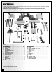
UNPACKING Carefully unpack and remove the shaper and its components from the box and check for damaged or missing items as per the list of contents below. NOTE: Please report any damaged or missing items to your General International distributor immediately. A B C D E J H F I G K P N O Q R M S L T HEAD LIST OF CONTENTS. . . . . . . . . . . . . . . . . . . . . . . . . . . . . . . . . . . . . . . . . . QTY ABCDEFGHIJKLM- SAFETY GUARD. . . . . . . . . . . . . . . . . . . . . . . . . . . . . .
PLACEMENT WITHIN THE SHOP / ESTABLISHING A SAFETY ZONE THIS MODEL 40-250 M1 3/4” SPINDLE SHAPER IS HEAVY. DO NOT OVER-EXERT. THE HELP OF AT LEAST ONE ASSISTANT OR A HOIST WILL BE NEEDED FOR THE FOLLOWING STEP. TO LIMIT THE RISK OF SERIOUS INJURY OR DAMAGE TO THE MACHINE, ANY EQUIPMENT USED TO LIFT THIS MACHINE SHOULD HAVE A RATED CAPACITY IN EXCESS OF 326 LBS (148 KG).
ASSEMBLY INSTRUCTIONS For your convenience this shaper is shipped from the factory partially assembled and requires only minimal assembly and set up before being put into service. B A C Place the guard on the table and tightened by two lock lever screws, A. D E Place the plate guard on top of guard and tightened by two knobs, D. Install the safety guard to front of plate guard and tightened by two knobs, E. in proper position.
BASIC ADJUSTMENTS & CONTROLS CONNECTING TO A POWER SOURCE Once the assembly steps have been completed, plug the power cord into an appropriate outlet. Refer back to the section entitled “ELECTRICAL REQUIREMENTS” and make sure all requirements and grounding instructions are followed. When cutting operations have been completed unplug the saw from the power source.
SPINDLE RAISING AND LOWERING B Adjust the main shaft to the up or down position. 1. Loosen the front hand wheel, A. 2. Turn the Hand wheel, B, to the desired height. 3. Tighten the hand wheel, A. SPINDLE ASSEMBLY CHANGING SPINDLES A 3/4" and 1/2” spindle assemblies are supplied with your shaper. The assemblies are locked in a tapered seat with a draw bar and nut.
OPERATING CONTROLS FOR THE FENCE Depending on the type of work you are shaping, either side of the fence can be moved freely. Fence can be moved by loosening wing screws, A, proper setting can be achieved by turning knob, B. The turning knob, B, is with scale for accurate setting. Wing screws, A, must be then tightened to fix in position. A C Each fence half should be adjusted as close to cutter head as possible. To position fence closer to cutter head, loosen handle, C.
TOOL CHANGING When changing tools, the process demands lots of attention and extra precautions, keep in mind the following procedures. 1. Spacers, cutters and collars mounted on the spindle shaft must be in a fixed position. There must be no move ment, space or touching between parts. 2. Counter bores and holes of collars, cutters or spacers must be in perfect condition with no rust or flaws. 3. Before installing the collars, cutters and spacers on the spindle they must be cleaned properly. 4.
STRAIGHT EDGE SHAPING The work piece must always be against the fence to perform straight edge shaping, follow these procedures to set up: 1. Disconnect machine from the power source. 2. Fence faces must be parallel, properly in line or offset If necessary, and securely tightened. 3. Cutter must be rotated and inspected for clearance. 90° 4. Position the leading face of a cutter head blade at 90° to the infeed fence and adjust the spindle to the desired height of the cut.
END SHAPING Scrap When end shaping narrow stock at least one half of the work piece end must be in contact with either the outfeed or infeed fence. NEVER ATTEMPT TO SHAPE A NARROW PIECE WITHOUT A SPECIAL GUIDE, THE WORK PIECE MAY STAR ROCKING INTO THE CUTTER HEAD CAUSING MINOR OR MAJOR INJURY TO THE WORK OPERATOR. SHAPING SIDES Workpiece ON-EDGE SHAPING 4th CUT 1st CUT 2st CUT Wide stock 3rd CUT When shaping across the grain, some woods are more likely to chip out or splinter.
Remove entire fence assembly; place jig carefully at the desired depth of cut, clamp to table securely. It is important with arc and circle shapes that the work piece must be roughly cut to desired size and curve of the finished piece, before being shaped. The curve of the jig must match the work piece exactly. The work piece must be firmly attached to the jig. This operation should always be in use of a ring guard or a similar safety device over the cutter head. NEVER ATTEMPT TO SHAPE FREEHAND.
SECURING A TEMPLATE TO THE WORK PIECE Various methods are used to secure template to the work piece. The operator should select the best method to secure the template to the work piece based on the size, shape, and constriction of the template and work piece. Handles Handles Workpiece Dowels “C” Clamps "C" clamps can be used to securely hold a template when the work piece is large enough to surpass the front of table, while still leaving space for the desired cut.
STACKED CUTTERS A variety of timesaving and interesting cuts can be made in a single setup by stacking the cutters, A. When stacking cutters extra care should be taken. Check that cutters have no flaw nicks, or just. Cutters must cleaned and perfectly balanced before placing in the stacked poisiton. A Cutter Stock Stock Collar Sash cutter Groove cutter Door shaping requires two operations, demonstrates sash cut for the first operation.
TENONING Figure A demonstrates the tenoning fixture which shows a miter gauge equipped with a hold-down for shaping the ends of narrow work piece. A Miter gauge can also be adapted to cut square and centered tenons at the ends of leg for table, chairs etc. Secure leg to the jig and position for cut, B. A First cuts must be made with the same jig setting and spindle height. When the first several cuts have been made, reposition the leg on the jig for each succeeding cut.
CABINET QUILL 61 67 68 69 63 24 25 25 46 62 40 66 54 42 64 65 59 54 60 45 14 26 46 13 26 27 56 28 79 46 55 54 29 14 15 53 58 57 51 49 15 13 52 25 30 31 32 33 15 13 34 50 41 40 42 .
SPINDLE 111 109 108 112 136 131 110 109 135 133 134 132 113 136 127 111 112 135 130 114 133 101 115 118 116 119 122 114 129 117 120 121 128 116 120 117 123 119 124 118 121 125 103 104 26 125 FENCE 103 126 22 103 26 126 102
PARTS LIST 40-250 PART N0.
MODEL 40-250 M1 8360 Champ-d’Eau, Montreal (Quebec) Canada H1P 1Y3 Fax: (514) 326-5565 - Tel.: (514) 326-1161 Fax: (514) 326-5555 - Parts & Service / Order Desk orderdesk@general.ca www.general.ca IMPORTANT When ordering replacement parts, always give the model number, serial number of the machine and part number. Also a brief description of each item and quantity desired.