SETUP & OPERATION MANUAL FEATURES Combination riving style splitter and seethrough blade guard with anti-kickback pawls, and a second European style riving knife also included. 10" LEFT TILT 2 HP TABLE SAW Large precision-ground 44” x 27” cast-iron table with two extension wings. 4” dust port allows easy connection to a dust collection system. Large paddle-style stop switch. Ruggedly built saw carriage with solid cast-iron cabinet mounted trunnions.
GENERAL® INTERNATIONAL 8360 Champ-d’Eau, Montreal (Quebec) Canada H1P 1Y3 Telephone (514) 326-1161 • Fax (514) 326-5555 • www.general.ca THANK YOU for choosing this General International model 50-200R 10" Left tilt 2 HP Table Saw. This saw has been carefully tested and inspected before shipment and if properly used and maintained, will provide you with years of reliable service.
GENERAL® MFG & GENERAL® INTERNATIONAL WARRANTY All component parts of General® MFG, General® International and Excalibur by General International ® products are carefully inspected during all stages of production and each unit is thoroughly inspected upon completion of assembly.
TABLE OF CONTENTS SAFETY RULES . . . . . . . . . . . . . . . . . . . . . . .5 ELECTRICAL REQUIREMENTS . . . . . . . . . . . . . .6 Grounding instructions . . . . . . . . . . . . . . . . . . . . . . .6 Circuit capacity . . . . . . . . . . . . . . . . . . . . . . . . . . . . .6 Converting the motor to 115V . . . . . . . . . . . . . . . . .6 Extension cords . . . . . . . . . . . . . . . . . . . . . . . . . . . . .6 IDENTIFICATION OF MAIN PARTS AND COMPONENTS . . . . . . . . . . . . . . . . . . . . . . .
RULES FOR SAFE OPERATION To help ensure safe operation, please take a moment to learn the machine’s applications and limitations, as well as potential hazards. General® International disclaims any real or implied warranty and holds itself harmless for any injury that may result from improper use of its equipment. 1. Do not operate the saw when tired, distracted, or under the effects of drugs, alcohol or any medication that impairs reflexes or alertness. 2.
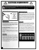
ELECTRICAL REQUIREMENTS BEFORE CONNECTING THE MACHINE TO THE POWER SOURCE, VERIFY THAT THE VOLTAGE OF YOUR POWER SUPPLY CORRESPONDS WITH THE VOLTAGE SPECIFIED ON THE MOTOR I.D. NAMEPLATE. A POWER SOURCE WITH GREATER VOLTAGE THAN NEEDED CAN RESULT IN SERIOUS INJURY TO THE USER AS WELL AS DAMAGE TO THE MACHINE. IF IN DOUBT, CONTACT A QUALIFIED ELECTRICIAN BEFORE CONNECTING TO THE POWER SOURCE. THIS TOOL IS FOR INDOOR USE ONLY. DO NOT EXPOSE TO RAIN OR USE IN WET OR DAMP LOCATIONS.
10" LEFT TILT 2 HP TABLE SAW 50-200R IDENTIFICATION OF MAIN PARTS AND COMPONENTS F C B A D G E I Q H J N O K P L M A- LEFT TABLE EXTENSION K- MITER GAUGE STORAGE BRACKET B- MITER GAUGE L- CABINET C- SPLITTER AND BLADE GUARD ASSEMBLY M- ARBOR WRENCH STORAGE BRACKET D- MAIN TABLE N- BEVEL SCALE E- RIGHT TABLE EXTENSION O- BLADE HEIGHT ADJUSTMENT HANDWHEEL F- RIP FENCE P- FENCE STORAGE BRACKET G- REAR RAIL Q- ON/OFF SWITCH H- FRONT RAIL I- RIP FENCE LOCKING HANDLE J- BLADE TILT A
BASIC FUNCTIONS This saw has been designed for cutting solid wood as well as manufactured wood materials such as plywood, wood panelling, particleboard, mdf and other wood based by-products. This saw is not designed for cutting metals nor for cutting any materials other than wood or wood based stock. This saw is designed for use with maximum 10" (250mm) diameter blades having a center hole diameter of 5/8".
PLACEMENT WITHIN THE SHOP / ESTABLISHING A SAFETY ZONE THIS MODEL 50-200R 10" LEFT TILT 2 HP TABLE SAW IS HEAVY. DO NOT OVER-EXERT. A HOIST OR FORKLIFT WITH STRAPS SHOULD BE USED TO LIFT THIS MACHINE. TO LIMIT THE RISK OF SERIOUS INJURY OR DAMAGE TO THE MACHINE, ANY EQUIPMENT USED TO LIFT THIS MACHINE SHOULD HAVE A RATED CAPACITY IN EXCESS OF 303 LBS (138KG).
ASSEMBLY INSTRUCTIONS SERIOUS PERSONAL INJURY COULD OCCUR IF YOU CONNECT THE MACHINE TO THE POWER SOURCE BEFORE YOU HAVE COMPLETED THE INSTALLATION AND ASSEMBLY STEPS. DO NOT CONNECT THE MACHINE TO THE POWER SOURCE UNTIL INSTRUCTED TO DO SO. INSTALL THE TABLE EXTENSION WINGS Attach the table extension wings to the main table using 6 hex head bolts (3 per wing) and 6 lock washers A. Align the table extensions with the table and loosely attach the bolts.
INSTALL THE FRONT FENCE RAIL A 12 mm B 10 mm C A 12 mm 1. Loosely attach the 4 L-brackets to the front of the table using a 12 mm hex head bolt with hex nut and flat washer on both extension wings, A, and 2 long 10 mm hex head bolts with hex nuts and flat washers on the main table B, in the assembly order shown. 2. Do not tighten down the nuts; the bolts should not be protruding from the L-brackets, C. D E F 3.
INSTALL / REMOVE A SAW BLADE NOTE This saw is intended for use with 10" (250mm) diameter or less saw blades having a center hole diameter of 5/8". There are many types of blades available to perform specific cutting jobs, such as crosscuts or ripping only, or for use with plywood, panelling and other products. A good quality specialty blade can produce a finer finish, be more efficient and place less strain on the saw. Use only saw blades designed for use at a maximum operating speed of 5000 RPM or less.
INSTALL AND ADJUST RIVING KNIFE SELECT A RIVING KNIFE Two riving knives are provided: - A combination riving style splitter and blade guard with anti-kickback pawls A; - A European style riving knife without blade guard B. The riving knife must always be used with a blade guard. If you already own an independently attached bladeguard such as our Excalibur 50-EXBC10, use the riving knife B. If you do not already own a blade guard, use the splitter/blade guard assembly A.
ALIGN THE RIP FENCE ALIGN THE RIP FENCE PARALLEL TO THE BLADE THE RIP FENCE MUST BE PARALLEL TO THE BLADE DURING OPERATION. FAILURE TO SET THE RIP FENCE PARALLEL TO THE BLADE CAN RESULT IN KICKBACK AND POSSIBLE SERIOUS INJURY. To make satisfactory rip cuts, your fence must be aligned perfectly parallel with the saw blade. 1. Slide the fence over to the right T-slot on your saw table top A.
INSTALL THE MEASURING TAPE AND POINTER A B 1. Using a Phillips screwdriver, attach the pointer / visor to the right side of the fence base as shown. 2. Set the blade to 90° and raise it to the maximum height A. 3. Put the fence on the rails and move it till it slightly touches the right side of the blade B. D E F G C 4. Lock down the fence C. 5. Make a pencil mark on the rail, in line with the pointer’s center mark, D. Then, unlock the fence and put is aside for now. 6.
10. Repeat steps 3 to 9 with the fence to the left of the blade this time, aligning the center mark of the pointer with the zero of the second half of the measuring tape, K. K Note: Recheck and, if necessary, readjust the left and right pointers against the zero-point of both measuring tapes whenever you change blades. Different blades have different thicknesses, which can throw off the pointer a few fractions.
ON/OFF SWITCH & SAFETY PIN A B The ON/OFF switch assembly A is equipped with a lock-out safety pin B. When the pin is installed through the green “on” button C, the machine cannot be started. C To start the machine Lift the red stop switch panel and remove the lock-out pin. Lower the stop panel and push the green “ON” button. Wait for the saw blade to reach full speed before cutting. To stop the machine Push on the RED “STOP” panel and wait for the blade to come to a complete stop.
OPERATING INSTRUCTIONS VERIFY ALL CHECK POINTS BEFORE STARTING. FAILURE TO COMPLY CAN RESULT IN SERIOUS INJURIES. • Make sure that the arbor nut is secure and that the blade is firmly tightened snug on the arbor. • Check that the blade angle and height lock knobs are tight. • If ripping, make sure the fence lock lever is engaged and that the fence is parallel to the blade. • If cross cutting, make sure the miter gauge is locked tight.
BEVEL RIPPING Bevel ripping is performed the same as ripping but with the saw blade set to an angle not perpendicular with the table surface. After changing the bevel angle verify the alignment of the guard and splitter; make sure there is clearance with the saw blade. RIPPING SMALL WORK PIECES Do not attempt rip cuts if the work piece is too small, as this will oblige you to place your hands too close to the blade and put you at serious risk of injury.
ADDING AN AUXILIARY FENCE TO THE MITER GAUGE LARGER VIEW To ensure a true 90° crosscut, especially with longer pieces of wood that need more support than the narrow miter gauge head can provide, an auxiliary wood fence can be attached. B A FRONT VIEW C Make sure the wood for the fence is straight, and not bowed. It should be about 2" wide and extend about 12" from either side of the miter head.
MAINTENANCE & ADJUSTMENTS MAKE SURE THE SAW HAS BEEN TURNED OFF AND UNPLUGGED FROM THE POWER SOURCE BEFORE PERFORMING ANY MAINTENANCE. PERIODIC MAINTENANCE • Inspect/test the ON/OFF switch before each use. Do not operate the saw with a damaged switch - replace a damaged switch immediately • Inspect the saw blade for damage or chipped teeth before each use. Replace a damaged or chipped blade immediately.
ADJUSTING THE BEVEL ANGLE POINTER The bevel pointer should read “0” when the blade is at 90° to the table. If not, with the blade set 90° vertical to the table, proceed as follows: C A B 1. Remove the handwheel by loosening the hand wheel lock knob A. Notes 22 2. Once the handwheel has been removed, loosen the Phillips head screw B on the pointer mounting bracket with a screwdriver and manually align the pointer C with the zero on the bevel scale, then retighten the screw and re-attach the handwheel.
RECOMMENDED OPTIONAL ACCESSORIES We offer a large variety of products to help you increase convenience, productivity, accuracy and safety when using your saw. Here’s a small sampling of optional accessories available from your local General International dealer. For more information about our products, please visit our website at www.general.ca Miter guide #50-EB3 Sliding Table #50-SLT60 or 50-SLT40 Quickly and easily finds any angle.
CABINET AND TABLE 2a 59 3 1a 2 60 61 75 6 119 67 66 95 60 114 7 61 60 115 73 61 63 8 138 113 117 64 69 94 9 132 128 139 139 67 66 65 111 4a 10 118 127 76 76 14 110 130 79 133 140 131 71 15 141 70 13 76 13 129 109 5 76 12 98 72 142 97 16 17 97 96 24 13A 134 11
119 121A 134 126 125 124 123 122 121 112 41a 85 84 91 83 73 27 6 42 86 62 7 91 43 28 26 31 82 33 87 56 68 58 66 65 54 37 32 87 90 93 55 76 35 114115 52 34 89 39 38 25 53 56 57 30 29 30 136 103 90 75 101 99 71 106 105 36 135 24 67 74 102 21 24 100 43 104 23 20 44 65 66 80 22 108 107 19 78 71 76 18 77 45 116 81 80 46 51 47 50 48 49 BLADE TILTING MECHANISM 25
PARTS LIST - 50-200R 26 PARTS N0. REF. N0.
PARTS LIST - 50-200R PARTS N0.
PARTS LIST - 50-200R PARTS N0. REF. N0.
FENCE & RAIL ASSEMBLY – 50200R-F43 F14 F30 F3a F34 F4 F32 F5 F14 F28 F1 F3 F36 F35 F2 3 F10 F18 14 F19 F13 F8 F9 F19 F22 F21 F15 F11 F6 F7 F12 F20 F15 F15 50200R-F44 - FENCE BODY ASSEMBLY F15 F29 F17 F24 F40 F37 F24 F16 F24 F33 F23 F24 F37 F41 F40 F27 F37 F42 F38 F29 F25 F27 F17 F40 F39 F26 F38 F25a F26 F25a F33 F26 F37 F25 F26 50200R-F45 - RAILS ASSEMBLY 29
FENCE & RAILS ASSEMBLY PARTS LIST - 50200R-F43 30 PARTS N0. REF. N0.
SPLITTER / BLADE GUARD ASSEMBLY – 50200R-A27 A21 A22 A31 A10 A29 A4 A23 A30 A10 A6 A7 A17 A9 A6 A30 A26a A14 A29 A26b A18 A28 A13 A10 A2 A5 A24 A19 A25 A19 A12 A10 A20 A12 A1 A8 A11 A10 A3 A10 PARTS LIST - 50200R-A27 REF. N0.
MODEL 50-200R M1 8360 Champ-d’Eau, Montreal (Quebec) Canada H1P 1Y3 Fax: (514) 326-5565 - Tel.: (514) 326-1161 Fax: (514) 326-5555 - Parts & Service / Order Desk orderdesk@general.ca www.general.ca IMPORTANT When ordering replacement parts, always give the model number, serial number of the machine and part number. Also a brief description of each item and quantity desired.