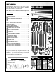
SETUP & OPERATION MANUAL FEATURES The table rides on 14 sealed, steel ball bearing rollers and is supported by architectural grade heavy-duty steel tubing. Easy to adjust, extruded aluminum miter fence for accurate miters from 0° to 45°. Adaptable to virtually all 10-14” table saws. SLIDING TABLE SLIDING TABLE ONLY TABLE SAW SOLD SEPARATELY New design sliding quick mount bracket for added cutting capacity. Cut up to 72”* with the crosscut fence positioned at the rear.
GENERAL® INTERNATIONAL 8360 Champ-d’Eau, Montreal (Quebec) Canada H1P 1Y3 Telephone (514) 326-1161 • Fax (514) 326-5555 • www.general.ca THANK YOU for choosing this Excalibur by General® International model 50-SLT60P Sliding Table. This sliding table has been carefully tested and inspected before shipment and if properly used and maintained, will provide you with years of reliable service.
GENERAL® MFG & GENERAL® INTERNATIONAL WARRANTY All component parts of General® MFG, General® International and Excalibur by General International ® products are carefully inspected during all stages of production and each unit is thoroughly inspected upon completion of assembly.
TABLE OF CONTENTS SAFETY RULES . . . . . . . . . . . . . . . . . . . . . . .5 IDENTIFICATION OF MAIN PARTS AND COMPONENTS . . . . . . . . . . . . . . . . . . . . . . .6 UNPACKING . . . . . . . . . . . . . . . . . . . . . . . .7 List of contents . . . . . . . . . . . . . . . . . . . . . . . . . . . . . .7 Additional requirements for set up . . . . . . . . . . . . .7 FINE TUNING ADJUSTMENTS . . . . . . . . . . . . .17 Leveling the sliding table with the saw table . . . .17 Install the rear outer leg mount .
Rules for Safe Operation To help ensure safe operation, please take a moment to learn the machine’s applications and limitations, as well as potential hazards. General International disclaims any real or implied warranty and hold itself harmless for any injury that may result from the improper use of it’s equipment. 1. Do not operate the saw when tired, distracted, or under the effects of drugs, alcohol or any medication that impairs reflexes or alertness. 2.
SLIDING TABLE 50-SLT60P IDENTIFICATION OF MAIN PARTS AND COMPONENTS RAIL & BRACE ASSEMBLY MAIN MOUNTING BRACKET QUICK MOUNT BRACKET CROSS BRACE (3X) FRONT OUTSIDE BRACKET (2X) REAR CROSS BRACE INNER GUIDE RAIL REAR INSIDE BRACKET FENCE STORAGE BRACKET (2X) SUPPORT LEG (4X) LEVELING FOOT (4X) REAR OUTSIDE BRACKET OUTER GUIDE RAIL TABLE & CROSS CUT FENCE ASSEMBLY CROSS CUT FENCE MITER CLAMP SLIDING FLIP-UP STOP ANGLE ADJUSTMENT RAIL RETURN HANDLE SLIDING TABLE 6
UNPACKING Carefully unpack and remove the unit and its components from the box and check for missing or damaged items as per the list of contents below. BOX 1 - FENCE & RAILS NOTE: Please report any damaged or missing items to your GENERAL® INTERNATIONAL distributor immediately. LIST OF CONTENTS QTY BOX 1 - FENCE & RAILS OUTER GUIDE RAIL . . . . . . . . . . . . . . . . . . . . . . . . . . . .1 INNER GUIDE RAIL . . . . . . . . . . . . . . . . . . . . . . . . . . . .1 FENCE WITH FENCE EXTENSION POST . .
PREPARATION BEFORE ASSEMBLY VERY IMPORTANT! BEFORE PROCEEDING WITH THE ASSEMBLY STEPS MAKE SURE THE SAW TABLE IS LEVELED WITH THE FLOOR, PLACING A LEVEL ON THE TABLE. USE SHIMS (OR LEVELING FEET IF APPLICABLE) FOR LEVELING IF NEEDED. REMOVE TABLE LEFT EXTENSION WING, RIP FENCE AND GUIDE RAILS For most installations, in order for the sliding table to be as close as possible to the blade the table extension wing must be removed.
CLOSE UP 2. Fit a support leg into the four brackets as shown then tighten with two hex bolts and flat washers. 3. Install a fence storage bracket legs as shown in . onto the two front Tip: Select the second hole from the top of the bracket as shown in to allow room for fine tuning adjustments later. STEP 2 - BRACKETS AND INNER RAIL INSTALLATION HARDWARE BAG 2* *All mounting hardware required for Assembly Step 2 can be found in hardware bag 2.
INNER RAIL UNDERSIDE VIEW - THREADED HOLES REAR INNER LEG MOUNT QUICK MOUNT BRACKET SWITCH MOUNT BRACKET REAR BRACKET MOUNT INNER RAIL SIDE VIEW - ACCESS HOLES FASTENER ACCESS HOLES (X6) SLIDING TABLE BEARING ACCESS HOLES ATTACH THE REAR INNER LEG MOUNT TO THE INNER GUIDE RAIL INNER REAR LEG MOUNT 1.
STEP 3 - CROSS BRACES INSTALLATION HARDWARE BAG 3* All mounting hardware required for Assembly Step 3 can be found in hardware bag 3. INSTALL THE REAR CROSS BRACE 1. Attach the rear bracket mount to the inner guide rail as shown in , using two hex bolts and washers . REAR BRACKET MOUNT 2. Attach the rear cross brace assembly to the rear bracket mount , using one hex bolt, 2 flat washers and a lock nut in the assembly order shown in . 3.
Final installation shown for clarity only 7. Attach the two front outside leg mounts to the cross braces as shown, using 6 shoulder bolts, flat washers and cap nuts . 8. Attach the outer rail to the leg mounts (with the wide polished surface closest to the table saw) as shown, using 4 hex bolts and washers from hardware bag 2. Note: The rear outer leg mount will be installed later, once the sliding table has been leveled with the saw table in the section “FINE TUNING ADJUSTMENTS”.
BEARING ADJUSTMENTS CLOSE UP PULL BACK TO LOCK 3. To eliminate the lateral play between the table and the outer rail, release the locking bolts on the eccentric adjusters from underside of the table. Using a 3/4” socket or wrench turn the eccentric adjusters to pre - load the bearings against the rail. DO NOT OVER LOAD the bearings to the rail. Tighten the eccentric adjusters locking bolts making sure the eccentric adjusters do not move. 4. The brake lever is also mounted on an eccentric adjuster.
9. Adjust the height of the bearings in the slotted hole in their bracket so that each bearing touches the bottom edge of the guide rail, then tighten the nuts to lock the bearings in place. 10. To eliminate the vertical play between the table and the inner rail, using the 6 mm "T" handle wrench supplied , locate and release the locking bolts on the eccentric adjusters (access through holes in inner rail ).
RAIL UNDERSIDE VIEW 3. Thread a t-nut on to one of the ratchet levers . Then slide the t-nut into the t-track , and locate the hole in the underside of the angle adjustment rail . 4. Thread a ratchet lever onto the fence pivot brackets at each end of the table. Note: This ratchet lever is used to secure the return handle. CROSS CUT FENCE ASSEMBLY 1. Sit the cross cut fence face down on the front* of the sliding table with holes facing upward. 2. Insert the plastic washer on the fence pivot post .
4. Side the t-nut on the miter clamp into the t-slot approximately 2' from the opposite end of the fence . 5. Fit the pivot post into the pivot post bracket . Note: The pivot post should protrude an equal distance from the top and bottom of its mounting bracket . Flush here 6. Slide the mitre clamp assembly along the fence until the t-nut lines up with the t-slot on the angle adjustment rail .
FINE TUNING ADJUSTMENTS To ensure the ability to make square and accurate repeat cuts the following fine tuning adjustment procedures should be performed after completing the assembly steps. VERY IMPORTANT! THE FOLLOWING ADJUSTMENTS WILL PROVIDE ACCURACY ONLY IF YOUR SAW TABLE IS LEVELED WITH THE FLOOR. USE SHIMS (OR LEVELING FEET IF IT HAS SOME) FOR LEVELING IF NEEDED. LEVELING THE SLIDING TABLE WITH THE SAW TABLE 1. Using a level, verify that the sliding table is leveled with the saw table . 2.
SETTING THE SLIDING TABLE TRACKING The sliding table must be set to run parallel to the blade (and not the mitre slot ) .Verify and, if needed, set the table tracking parallel to the blade as follows: Note: For the following step you will need a straightedge (a minimum of 30" long and preferably as long as possible). If you don’t own one, you can always use your saw rip fence. TURN OFF AND UNPLUG THE SAW BEFORE PERFORMING ANY ADJUSTMENTS.
RAIL UNDERSIDE VIEW 4. To adjust the outer rail, loosen the 2 bolts and center outer leg bracket . on the front 5. Manually adjust either the front or rear end of the outer rail towards the saw then retighten the leg bracket bolts. 6. Slowly slide the table front to back and verify the table tracking again. If needed, make further adjustments until the table is tracking parallel to the straightedge.
CLOSE UP 3. Loosen the miter clamp and adjust the cross cut fence to the perpendicular face of your machinists square . Then secure the cross cut fence in position by tightening the miter clamp. 4. Adjust the sliding angle indicator (degree scale) by loosening the lock bolt and manually aligning it to “0” with the front face of the cross cut fence and then re-tighten the lock bolt.
SET THE 90º STOP WITH THE FENCE IN THE REAR POSITION In order to make repeatable square cuts the crosscut fence must be set 90° perpendicular to the blade with the fence mounted in both front & rear positions. To align the cross cut fence in the rear mount position reverse the fence to rear position as follows. , TURN OFF AND UNPLUG THE SAW BEFORE PERFORMING ANY ADJUSTMENTS. 1. If installed, remove the extension from the cross-cut fence. 2.
Once the cross cut fence has been reversed to rear position, verify and, if needed, adjust the alignment of the cross cut fence for rear mounted position. You will then be able to set the 90° stop as follows, to allow the cross cut fence to be brought back perpendicular to the blade whenever needed and without having to further realign the fence each time. 1. Loosen the hex bolt block . and remove the 90° locator 2.
To set the sliding scale and permit accurate measurements using the flip stop: 1/4” 1. Set the fence to approximately 1/4" from the blade and secure it using the ratchet levers of both the miter clamp and pivot post. 2. Align the sliding scale flush to the end of the fence. 10” 3. Secure the sliding scale by tightening the locking bolt. 4. Position the sliding flip-up stop at any dimension on the scale, i.e. 10”.
VERIFY ALL FOLLOWING CHECK POINTS BEFORE TURNING ON THE SAW. FAILURE TO COMPLY CAN RESULT IN SERIOUS INJURIES. CHECK POINTS • Make sure that the arbor nut is secure and that the blade is firmly tightened snug on the arbor. • Check that the blade angle and height lock knobs are tight. • While using the saw, be sure to wear safety glasses at all times. • Make sure that the blade guard/splitter assembly is properly installed and aligned with the blade, and that the anti-kickback pawls are functioning.
DO NOT USE RIP FENCE AS A GUIDE OR WORKPIECE STOP WHEN OPERATING THE SLIDING TABLE. TO AVOID POTENTIAL OF WORKPIECE BINDING WHICH WILL CAUSE KICKBACK, REMOVE THE RIP FENCE FROM THE SAW COMPLETELY. FENCE IN REAR POSITION 1. Set the cross-cut fence to the rear of the sliding table (Maximum capacity position). 2. Loosen the two ratchet levers . 3. Slide the cross-cut fence to within 1/4" of the blade , then tighten the ratchet levers to secure the cross-cut fence so it does not move during the cut. 4.
MITER CUTS FENCE IN FRONT POSITION With the cross-cut fence positioned at the front of the table (front position), you can cut a maximum of 36"* and make miter cuts from 0° to 45°. * Depending on the positioning of the quick mount bracket on your saw. NOTE: To reposition cutting capacity, slide the quick mount bracket towards the front of the saw. See the explanatory note at the bottom of this page.
RECOMMENDED OPTIONAL ACCESSORIES Here are some of the optional accessories available from your local General International dealer. For more information about our products, please visit our website at www.general.ca SLIDING FLIP-UP WORKSTOP #50-EXSTOP HOLD DOWN CLAMP #50-EXHDC Sliding flip stop for cross cut fence on Excalibur sliding tables. Fits in the t-slot of the cross cut fence on your Excalibur sliding table.
76 71 40 40 71 67 40 71 55 71 68 69 71 40 51 52 52 54 53 51 53 76 71 40 40 71 67 40 71 55 71 68 69 71 40 49 67 71 40 40 71 14 40 71 73 10 17 18 71 45 56 40 71 70 68 69 71 40 46 57 47 81 10 48 9 77 77 52 51 53 77 72 74 71 92 54 71 77 60 71 78 93 71 40 79 54 59 49 100 75 40 71 40 92 71 93 71 52 51 53 101 68 69 71 67 71 40 40 71 SUPPORT SYSTEM
1 2 10 11 5 7 6 13 10 17 18 6 26 11 15 12 10 9 97 20 9 11 97 25 10 18 9 10 8 13 17 19 97 6 13 13 10 21 16 18 10 11 4 3 7 22 10 9 M 13 98 10 23 15 8 9 19 99 19 25 18 8 26 10 12 17 18 8 13 19 96 10 9 10 10 18 18 17 24 17 10 18 9 90 19 17 10 10 8 96 17 18 58 10 7 19 23 10 22 TABLE ASSEMBLY 29
35 85 91 89 32 84 83 82 33 94 102 88 31 80 95 38 27 6 7 6 28 30 41 32 39 34 29 86 62 M 50 33 36 61 37 63 38 87 6 6 65 13 63 66 64 29 44 43 42 CROSS CUT FENCE
PARTS LIST 50-SLT60P REF. N0. PART N0.
PARTS LIST 50-SLT60P 32 REF. N0. PART N0.
NOTES 33
MODEL 50-SLT60P 8360 Champ-d’Eau, Montreal (Quebec) Canada H1P 1Y3 Fax: (514) 326-5565 - Tel.: (514) 326-1161 Fax: (514) 326-5555 - Parts & Service / Order Desk orderdesk@general.ca www.general.ca IMPORTANT When ordering replacement parts, always give the model number, serial number of the machine and part number. Also a brief description of each item and quantity desired.