
Use and Care Manual


8
VERY IMPORTANT!
BEFORE PROCEEDING WITH THE ASSEMBLY STEPS MAKE SURE THE SA
W TABLE IS LEVELED WITH THE
FLOOR, PLACING A LEVEL ON THE TABLE. USE SHIMS (OR LEVELING FEET IF APPLICABLE) FOR LEVELING
IF NEEDED.
PREPARATION BEFORE ASSEMBLY
REMOVE T
ABLE LEFT EXTENSION WING, RIP FENCE AND GUIDE RAILS
For most installations, in order for the sliding table to be as close as possible to the blade the table extension wing
must be removed. To avoid interfering with the movement of the sliding table, the rip fence guide rails will also need
to be temporarily removed and may need to be shortened so that they do not protrude beyond the end of the main
table.
1. Make a reference mark on the rip fence guide rails
even with the end of the main table (not the exten-
sion wing and then remove and set aside the
fence and rails .
2. Remove the left extension wing from the main
table and set it aside.
Note: Do not cut the fence rails just yet - wait until you are ready to re-install the fence after assembling, installing
and aligning the sliding table. Some fence systems may allow you to simply slide or re-mount the guide rails further
to the right, allowing you to increase the rip cutting capacity of the saw to the right of the blade.
1.
Install a leveling foot , a hex nut , and a flat wash-
er to the bottom of all four support legs , as shown
in .
Tip: Leave a space of approximately 1" between the feet and
legs as shown in to facilitate the leveling of the sliding
table with the saw table when you proceed to fine tuning
adjustments later.
*All mounting hardware required for Assembly Step 1 can be found in hardware bag 1.
NOTE: Adjustments made during the initial set-up phase may be approximate. Once the table is assembled you
will be able to make minor adjustments for leveling and fine tuning at that time.
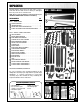
HARDWARE BAG 1*
STEP 1 - LEGS AND BRACKET PRE-ASSEMBLY
1”