SETUP & OPERATION MANUAL FEATURES Forced opening line interrupter switch, requires machine restart in case of power failure or circuit interruption. 12" VARIABLE SPEED DRILL PRESS - BENCH TOP Adjustable spindle tension return spring. Built-in laser pointer. Sturdy design with cast-iron head, base, and table. High-quality bearings for smooth, vibration-free operation. Simple hand lever controlled mechanical variable speed from 500 to 3000 rpm. Digital spindle speed display.
GENERAL® INTERNATIONAL 8360 Champ-d’Eau, Montreal (Quebec) Canada H1P 1Y3 Telephone (514) 326-1161 • Fax (514) 326-5555 • www.general.ca THANK YOU for choosing this General® International model 75-010 drill press. This drill press has been carefully tested and inspected before shipment and if properly used and maintained, will provide you with years of reliable service.
GENERAL® INTERNATIONAL WARRANTY All component parts of General® International and Excalibur by General International® products are carefully inspected during all stages of production and each unit is thoroughly inspected upon completion of assembly.
TABLE OF CONTENTS Rules for safe operation...................................................................................................... 5 Electrical requirements....................................................................................................... 6 Grounding instructions........................................................................................................................................ 6 Circuit capacity...........................................................
RULES FOR SAFE OPERATION To help ensure safe operation, please take a moment to learn the machine’s applications and limitations, as well as potential hazards. General® International disclaims any real or implied warranty and holds itself harmless for any injury that may result from the improper use of it’s equipment. 1. Do not operate the drill press when tired, distracted, or under the effects of drugs, alcohol or any medication that impairs reflexes or alertness. 2.
ELECTRICAL REQUIREMENTS BEFORE CONNECTING THE MACHINE TO THE POWER SOURCE, VERIFY THAT THE VOLTAGE OF YOUR POWER SUPPLY CORRESPONDS WITH THE VOLTAGE SPECIFIED ON THE MOTOR I.D. NAMEPLATE. A POWER SOURCE WITH GREATER VOLTAGE THAN NEEDED CAN RESULT IN SERIOUS INJURY TO THE USER AS WELL AS DAMAGE TO THE MACHINE. IF IN DOUBT, CONTACT A QUALIFIED ELECTRICIAN BEFORE CONNECTING TO THE POWER SOURCE. THIS TOOL IS FOR INDOOR USE ONLY. DO NOT EXPOSE TO RAIN OR USE IN WET OR DAMP LOCATIONS.
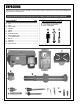
IDENTIFICATION OF MAIN PARTS AND COMPONENTS H G I F E D J C K B L A A. BASE G. SWITCH B. COLUMN H. PULLEY COVER C. TABLE I. D. FLIP-UP CHUCK GUARD J. FEED HANDLE E. LASER POINTER SWITCH K. TABLE CRANK HANDLE F. L.
UNPACKING Carefully unpack and remove the unit and its components from the box and check for missing or damaged items as per the list of contents below. NOTE: PLEASE REPORT ANY DAMAGED OR MISSING ITEMS TO YOUR GENERAL® INTERNATIONAL DISTRIBUTOR IMMEDIATELY. L IST OF CONTENTS QTY A. HEAD STOCK............................................................................. 1 B. BASE.......................................................................................... 1 C. TABLE...........................
CLEANING The protective coating on the machine prevents rust from forming during shipping and storage. Remove it by rubbing with a rag dipped in kerosene, mineral spirits or paint thinner. (Dispose of potentially flammable solvent-soaked rags according to manufacturer’s safety recommendations). A putty knife, held flat to avoid scratching the surface, may also be used to scrape off the coating followed by clean-up with solvent.
BEFORE ASSEMBLING, MAKE SURE THAT THE SWITCH IS IN THE “OFF” POSITION AND THAT THE POWER CORD IS UNPLUGGED. DO NOT PLUG IN OR TURN ON THE MACHINE UNTIL YOU HAVE COMPLETED THE ASSEMBLY AND INSTALLATION STEPS DESCRIBED IN THIS SECTION OF THE MANUAL. INSTALLING THE COLUMN ON THE BASE 1. Set the base on a flat and stable surface, and then install the column on the base. 2. Align the mounting holes in the column with the corresponding holes in the base. Tighten the four bolts by hand A few turns. 4.
BEFORE ASSEMBLING, MAKE SURE THAT THE SWITCH IS IN THE “OFF” POSITION AND THAT THE POWER CORD IS UNPLUGGED. DO NOT PLUG IN OR TURN ON THE MACHINE UNTIL YOU HAVE COMPLETED THE ASSEMBLY AND INSTALLATION STEPS DESCRIBED IN THIS SECTION OF THE MANUAL. A B 3. Center the head stock with the column and the table. 4. Secure the head stock to the column by tightening screws A & B using a 5 mm Allen key. 2. Hold the table against the bracket aligning the mounting holes as shown. INSTALLING THE TABLE A 1.
MAKE SURE THE MACHINE HAS BEEN TURNED OFF AND UNPLUGGED FROM THE POWER SOURCE BEFORE PERFORMING ANY MAINTENANCE OR ADJUSTMENTS. E D 5. Tighten the arm's mounting bolt using a wrench. 6. Slide handle D onto the arbor as shown E. F G 7. Tighten the set screw F using a 4 mm Allen key. 8. Lock the table in position by tightening the lever G as shown. 2. Tighten the chuck guard using a phillips screwdriver. INSTALLING THE CHUCK GUARD A 1. 12 Slide the chuck guard onto its support as shown A.
MAKE SURE THE MACHINE HAS BEEN TURNED OFF AND UNPLUGGED FROM THE POWER SOURCE BEFORE PERFORMING ANY MAINTENANCE OR ADJUSTMENTS. INSTALLING THE DOWNFEED HANDLES B 1. Thread the three downfeed handles into their mounting holes located in the support B. 2. Tighten each handle using a 9 mm wrench. 2. Tighten the handle using a 9 mm wrench. 2. Clean inside the chuck with a dry cloth until all grease or lubricant is removed. INSTALLING THE SPEED CONTROL LEVER C 1.
MAKE SURE THE MACHINE HAS BEEN TURNED OFF AND UNPLUGGED FROM THE POWER SOURCE BEFORE PERFORMING ANY MAINTENANCE OR ADJUSTMENTS. 3. Fit the arbor into the chuck as shown. 4. Make sure the arbor is inserted all the way into the chuck. 5. Slide the arbor into the quill assembly as shown. 6. Using the feed handles, lower the chuck against a piece of wood on the table to pressfit it into the quill. REMOVING THE CHUCK A C D B 1. Using feed handle, lower the quill assembly A.
MAKE SURE THE MACHINE HAS BEEN TURNED OFF AND UNPLUGGED FROM THE POWER SOURCE BEFORE PERFORMING ANY MAINTENANCE OR ADJUSTMENTS. INSTALLING A DRILL BIT E 1. F Open the chuck by turning the key E counterclockwise until you can insert a drill bit F. 2. Secure the drill bit in the chuck by turning the key clockwise. BASIC ADJUSTMENTS & CONTROLS TO REDUCE THE RISK OF SHOCK OR FIRE DO NOT OPERATE THE UNIT WITH A DAMAGED POWER CORD OR PLUG. REPLACE DAMAGED CORD OR PLUG IMMEDIATELY.
MAKE SURE THE MACHINE HAS BEEN TURNED OFF AND UNPLUGGED FROM THE POWER SOURCE BEFORE PERFORMING ANY MAINTENANCE OR ADJUSTMENTS. ADJUSTING THE CHUCK GUARD HEIGHT D 1. Loosen the wing nuts D. 2. Position the shield at the desired height, then retighten the wing nuts. ADJUSTING THE DEPTH STOP This drill is equipped with an adjustable depth stop to allow repetitive drilling to a set depth.
MAKE SURE THE MACHINE HAS BEEN TURNED OFF AND UNPLUGGED FROM THE POWER SOURCE BEFORE PERFORMING ANY MAINTENANCE OR ADJUSTMENTS. ADJUSTING TABLE HEIGHT 1. Loosen the column lock handle as shown. 2. Turn the crank handle as shown until the table is at the desired height, then retighten the column lock handle. 2. Tilt the table to the desired angle, and then retighten the nut A. TABLE TILT ADJUSTMENT A 1.
MAKE SURE THE MACHINE HAS BEEN TURNED OFF AND UNPLUGGED FROM THE POWER SOURCE BEFORE PERFORMING ANY MAINTENANCE OR ADJUSTMENTS.
MAKE SURE THE MACHINE HAS BEEN TURNED OFF AND UNPLUGGED FROM THE POWER SOURCE BEFORE PERFORMING ANY MAINTENANCE OR ADJUSTMENTS. A 3. Secure the workpiece in a vise (optional). 4. For precision drilling use the laser pointer to locate the drilling point on the workpiece. 5. Turn ON the machine and adjust the speed. 6. Use the downfeed handles to lower the bit into the workpiece. MAINTENANCE BELT REPLACEMENT Inspect the belts afler every 100 hours of use.
MAKE SURE THE MACHINE HAS BEEN TURNED OFF AND UNPLUGGED FROM THE POWER SOURCE BEFORE PERFORMING ANY MAINTENANCE OR ADJUSTMENTS. 3. Slip a portion of the belt off and turn the pulley by hand until the belt comes off the pulley completely. 4. To install a new belt, put it between the flanges of the drive pulley. Pull back on the belt to make sure it is seated properly on the pulley. 6. Turn the pulley by hand until the belt tensions and snaps into place.
RECOMMENDED OPTIONAL ACCESSORIES item #70-025 25 PIECE DRUM SANDING KIT item #70-030 Turn your drill press into a mini drum sander. 5 different sized drums: 1/2”, 3/4”, 1”, 1-1/2” & 2” plus 2 sets of 80 grit and 2 sets of 120 grit, sanding sleeves for each. 10 piece replacement abrasive sleeve set for 70-025. Includes 5 (one of each size) 80 & 120 grit sanding sleeves. ABRASIVE SLEEVES Item #70-105 9” AUGER DRILL BIT SET Item #70-125 Heavy duty carbon steel.
DIAGRAM 75-010 22
PARTS LIST 75-010 IMPORTANT: When ordering replacement parts, always give the model number, serial number of the machine and part number. Also a brief description of each item and quantity desired.
8360 Champ-d’Eau, Montreal (Quebec) Canada H1P 1Y3 Tel.: (514) 326-1161 Fax: (514) 326-5565 - Parts & Service / (514) 326-5555 - Order Desk orderdesk@general.ca www.general.