Rotating, 45° tilting, crank-operated work-table with quick release clamp. Large front mounted stop switch with lock-out safety feature to prevent unwanted or unintentional start-up. Adjustable spindle tension return spring. Built-in lamp illuminates the drilling area. Spindle is supported by high quality ball bearings. Cast iron pulleys reduce vibration. Industrial 1/2 HP motor. Heavy-duty positive depth stop for quick adjustment. 5/8” drill chuck.
GENERAL® INTERNATIONAL 8360 Champ-d’Eau, Montreal (Quebec) Canada H1P 1Y3 Telephone (514) 326-1161 • Fax (514) 326-5555 • www.general.ca THANK YOU for choosing this General International model 75-150/75-160 drill press. This drill has been carefully tested and inspected before shipment and if properly used and maintained, will provide you with years of reliable service.
GENERAL® & GENERAL® INTERNATIONAL WARRANTY All component parts of General®, General® International and Excalibur by General International ® products are carefully inspected during all stages of production and each unit is thoroughly inspected upon completion of assembly.
RULES FOR SAFE OPERATION To help ensure safe operation, please take a moment to learn the machine’s applications and limitations, as well as potential hazards. General® International disclaims any real or implied warranty and holds itself harmless for any injury that may result from improper use of its equipment. 1. Do not operate the drill press when tired, distracted, or under the effects of drugs, alcohol or any medication that impairs reflexes or alertness. 2.
ELECTRICAL REQUIREMENTS BEFORE CONNECTING THE MACHINE TO THE POWER SOURCE, VERIFY THAT THE VOLTAGE OF YOUR POWER SUPPLY CORRESPONDS WITH THE VOLTAGE SPECIFIED ON THE MOTOR I.D. NAMEPLATE. A POWER SOURCE WITH GREATER VOLTAGE THAN NEEDED CAN RESULT IN SERIOUS INJURY TO THE USER AS WELL AS DAMAGE TO THE MACHINE. IF IN DOUBT, CONTACT A QUALIFIED ELECTRICIAN BEFORE CONNECTING TO THE POWER SOURCE. THIS TOOL IS FOR INDOOR USE ONLY. DO NOT EXPOSE TO RAIN OR USE IN WET OR DAMP LOCATIONS.
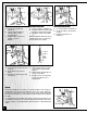
14” OR 16” DRILL PRESSES 75-150 • 75-160 A S S E M B LY I N S T R U C T I O N S Before proceeding with the assembly, read the operating and maintenance instructions manual and familiarize yourself with correct assembly, setup, maintenance and safety procedures. TO AVOID RISK OF SERIOUS INJURY, MAKE SURE THE DRILL PRESS IS INSTALLED ON A FLAT, SOLID AND STABLE SURFACE. 1. Place the base (1) on a flat surface and screw the column (8), to the base. 2. Remove the rack ring (9) from the column (8). 3.
INSTALLING THE CHUCK 1. Slide the arbor into the quill assembly, flat end goes in first. 2. Slide the chuck onto the tapered end of the arbor and using the feed handle, lower the quill assembly against the table to secure the chuck. (To avoid damaging the chuck place a piece of wood on the table.) Quill Assembly Tool Arbor Chuck REMOVING THE CHUCK AND ARBOR 1. Turn “OFF” and disconnect the drill from the power source. 2. Using feed handle, lower the quill assembly. 3.
ADJUSTING TABLE HEIGHT TABLE SWING ADJUSTMENT TABLE ROTATION ADJUSTMENT 1. 1. Loosen column lock handle (1). 1. Loosen the table lock handle (3). 2. 2. Turn the crank handle (2) until the table is at the desired height. Swing the table arm bracket and the table to the desired position. Rotate the table to the desired position. 3. Retighten column lock handle (1). 3. Retighten the table lock handle (3). Retighten the column lock handle (1) before starting.
CHANGING SPEEDS MAKE SURE THE DRILL PRESS HAS COME TO A COMPLETE STOP BEFORE CHANGING SPEEDS. REFER TO THE SPINDLE SPEED SELECTION CHART LOCATED ON THE INSIDE OF THE SPINDLE COVER. 1. Disconnect the drill press from the power source. 2. Loosen the slide bar bolt (1) located on the right side of the head. 3. Pull the motor (2) in towards the head to loosen the belts. 4. Relocates belts to the desired pulleys to select a new spindle speed. 5. Push the motor (2) back, away from the head. 6.
RECOMMENDED OPTIONAL ACCESSORIES We offer a large variety of products to help you increase convenience, productivity, accuracy and safety when using your drill press Here’s a small sampling of optional accessories available from your local General International dealer. For more information about our products, please visit our website at www.general.ca 25 PIECE - RUBBER DRUM SANDING SET #75-025 Turn your drill press into a mini drum sander. Ideal for small sanding jobs on curved or odd shaped pieces.
PARTS LIST 75-150 PART N0.
PARTS LIST 75-150 12 PART N0.
DIAGRAM 75-150 64 65 66 EA 40 68 67 SID 69 62 63 80 85(2) 78 77(2) 79 81 75 76 40-1 61 72 84 60 83 86 82 71 59 32-1 73 33 34 74 40-1 30(2) 31 32 EA SID 58(2) 57 29(4) 56(2) 28-1 28 27 40 36(3) 26-1 35N26-2 26 41 39(3) 37 25 23(3) 24N 42 44 45 38N 43 22N(3) 21 46 43 92 20 47 89 41 90 91 48 51 19 50 18N 52 49 53 10 49-1 11 87 54 7-1 9 12-1 55 8 12 88 17 7 6 4 16 5 13 15 14 3(4) 2(4) 1 13
PARTS LIST 75-160 14 PART N0.
PARTS LIST 75-160 PART N0.
DIAGRAM 75-160 64 65 66 68 67 69 62 63 40 80 85(2) 61 72 75 76 40-1 78 81 77(2) 79 82 60 84 83 86 71 32-1 73 33 74 40 41 34 36(3) E SID 31 32 A 58(2) 30(2) 29(4) 28-1 35N 26-2 28 26-1 26 25 44 45 38N 43 43 24N 22N(3) 92 20 47 89 90 91 41 48 19 50 52 87 23(3) 21 46 51 53 18 N 49 49-1 10 11 54 7-1 55 9 12-1 12 88 17 16 13 15 4 8 7 6 5 14 3(4) 2(4) 1 16 57 56(2) 27 39(3) 37 42 59 40-1
NOTES: 17
75-150 & 75-160 8360 Champ-d’Eau, Montreal (Quebec) Canada H1P 1Y3 Fax: (514) 326-5565 - Tel.: (514) 326-1161 Fax: (514) 326-5555 - Parts & Service / Order Desk orderdesk@general.ca www.general.ca IMPORTANT When ordering replacement parts, always give the model number, serial number of the machine and part number. Also a brief description of each item and quantity desired.