SETUP & OPERATION MANUAL FEATURES Designed for excellent results, for both wood and metal cutting applications. 17” WOOD / METAL BANDSAW Select between metal & wood cutting speed ranges with a simple belt position change. Dynamically balanced cast-iron wheels. Solid, high quality, precision-machined, ribbed cast-iron table with 5° left and 45° right tilting action. New and improved! Now includes upgraded 90-075B deluxe Excalibur rip fence system. Quick release blade tension lever.
GENERAL® INTERNATIONAL 8360 Champ-d’Eau, Montreal (Quebec) Canada H1P 1Y3 Telephone (514) 326-1161 • Fax (514) 326-5555 • www.general.ca THANK YOU for choosing this General International model 90-320 - 17” Wood / Metal Bandsaw. This bandsaw has been carefully tested and inspected before shipment and if properly used and maintained, will provide you with years of reliable service.
GENERAL® & GENERAL® INTERNATIONAL WARRANTY All component parts of General®, General® International and Excalibur by General International ® products are carefully inspected during all stages of production and each unit is thoroughly inspected upon completion of assembly.
TABLE OF CONTENTS Rules for safe operation . . . . . . . . . . . . . .5-6 Electrical requirements . . . . . . . . . . . . . . .7 Grounding instructions . . . . . . . . . . . . . . . . . . . . . . .7 Circuit capacity . . . . . . . . . . . . . . . . . . . . . . . . . . . . .7 Extension cords . . . . . . . . . . . . . . . . . . . . . . . . . . . . .7 Blade speed control . . . . . . . . . . . . . . . . . . . . . . . .22 Changing blade speed range - switching from wood to metal cutting . . . . . . . . . . . . .
RULES FOR SAFE OPERATION To help ensure safe operation, please take a moment to learn the machine’s applications and limitations, as well as potential hazards. General® International disclaims any real or implied warranty and holds itself harmless for any injury that may result from improper use of its equipment. 1. For your own safety read the instruction manual before operating this band saw. 14. Do not remove jammed cutoff pieces until blade has stopped. 2. This tool is for indoor use only.
RULES FOR SAFE OPERATION (CONT’D) To help ensure safe operation, please take a moment to learn the machine’s applications and limitations, as well as potential hazards. General® International disclaims any real or implied warranty and holds itself harmless for any injury that may result from improper use of its equipment. 27. Make sure that the switch is in the “OFF” position before plugging in the power cord. 28 Never leave the machine unattended while it is running or with the power on.
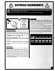
ELECTRICAL REQUIREMENTS BEFORE CONNECTING THE MACHINE TO THE POWER SOURCE, VERIFY THAT THE VOLTAGE OF YOUR POWER SUPPLY CORRESPONDS WITH THE VOLTAGE SPECIFIED ON THE MOTOR I.D. NAMEPLATE. A POWER SOURCE WITH GREATER VOLTAGE THAN NEEDED CAN RESULT IN SERIOUS INJURY TO THE USER AS WELL AS DAMAGE TO THE MACHINE. IF IN DOUBT, CONTACT A QUALIFIED ELECTRICIAN BEFORE CONNECTING TO THE POWER SOURCE. THIS TOOL IS FOR INDOOR USE ONLY. DO NOT EXPOSE TO RAIN OR USE IN WET OR DAMP LOCATIONS.
17” WOOD / METAL BANDSAW 90-320 IDENTIFICATION OF MAIN PARTS AND COMPONENTS FRONT VIEW HOISTING EYEBOLT LASER LINE MARKER BLADE TENSION WINDOW DIGITAL SPEED DISPLAY VARIABLE SPEED CONTROL KNOB ON/OFF SWITCH WITH SAFETY KEY RIP FENCE SYSTEM MITER GAUGE BLADE GUARD WORKLIGHT BLADE GUARD HEIGHT ADJUSTMENT HAND WHEEL BLADE TRACKING WINDOW 8 REAR VIEW BLADE TENSION QUICK RELEASE LEVER BLADE GUARD LOCK KNOB BLADE TRACKING ADJUSTMENT LEVER BLADE TRACKING ADJUSTMENT KNOB BLADE TENSION ADJUSTMENT HAND WHEEL TAB
BASIC FUNCTIONS This model 90-320 electronic variable speed 17” bandsaw is designed to allow the user to adjust the speed of the blade to suit different wood or metal cutting needs. This unit includes all of the basic functions and features found on similar size bandsaws. Featuring a front mounted digital blade speed display (in feet per minute) the unit is equipped with two speed ranges.
UNPACKING Carefully unpack and remove the unit and its components from its shipping container and check for missing or damaged items as per the list of contents below. SAW, TABLE & OTHER COMPONENTS* NOTE: Please report any damaged or missing items to your GENERAL® INTERNATIONAL distributor immediately. LIST OF CONTENTS QTY BOX 1 - EXCALIBUR RIP FENCE Note: Deluxe Excalibur Universal rip fence system is packed separately.
PLACEMENT WITHIN THE SHOP / ESTABLISHING A SAFETY ZONE PLACEMENT WITHIN THE SHOP This machine should be installed and operated only on a solid, flat and stable floor that is able to support the weight of the bandsaw 440 lbs (200 kg) and the operator. Using the dimensions shown as a guideline, plan for placement within your shop that will allow the operator to work unencumbered and unobstructed by foot traffic (either passing shop visitors or other shop workers) or other tools or machinery.
ASSEMBLY INSTRUCTIONS For your convenience this bandsaw is shipped from the factory partially assembled and requires only minimal assembly and set up before being put into service. Serious personal injury could occur if you connect the machine to the power source before you have completed the installation and assembly steps. DO NOT connect the machine to the power source until instructed to do so. INSTALL THE TABLE 1. To limit the risk of damage to the saw blade or frame, remove the blade.
TABLE UNDERSIDE VIEW 3. Lower the table until it sits on top of the bolt. 4. Place a combination square flat on the table with the heel of the square flat against the saw blade. 4. If the pointer needs to be adjusted, loosen the screw on the pointer of the front trunnion and adjust the pointer to the 0 point on the scale. Then re-tighten the screw to secure the pointer in place. CLOSE UP 3. Level the table until it is exactly 90° to the saw blade then tighten the jam nut against the saw cabinet .
INSTALL THE LASER LINE MARKER The laser line marker will allow you to easily mark a straight cut line on your workpiece. 1. Thread the shorter button head bolt side of the upper cabinet. from the in- 3. Loosely screw the longer button head bolt . 2. Attach the mounting bracket to the front of the saw using the socket screw through the door and the flange nut on the inside of the door. 4.
INSTALL THE FENCE ASSEMBLY This model 90-320 M1 is equipped with an Excalibur T-fence and guide rail system. Follow all assembly and adjustment instructions in the 90-075B manual supplied in the box with the Excalibur Universal Bandsaw Rip Fence System. BASIC ADJUSTMENTS AND CONTROLS ON/OFF SWITCH & SAFETY PIN LOCK-OUT POWER SWITCH OFF The ON/OFF switch assembly is equipped with a lockout safety pin . When the pin is installed through the green “on” button , the machine cannot be started.
CONNECTING TO A POWER SOURCE To avoid risk of shock or fire do not operate the unit with a damaged power cord or plug. Replace damaged cord or plug immediately. 1. Uncoil the power cord and plug it into an appropriate outlet (refer back to section “Electrical Requirements" and make sure all requirements and grounding instructions are followed). To avoid unexpected or unintentional start-up, make sure that both of the power switches are in the the OFF position before connecting to a power source.
WORKLIGHT The goose neck style worklight on this model 90-320 provides extra lighting for added convenience. It can be repositionned for optimal lighting of the work surface. Note: Uses a standard 40 Watt (maximum) 120 volt appliance bulb - Not Included. To reduce the risk of fire, use 40 Watt (maximum) 120 volt appliance bulb. Do not use standard household bulbs.
To remove a blade: Before replacing or adjusting the blade, make sure that both of the power switches are in the “OFF” position and that the power cord is unplugged. Blade teeth are sharp. Use care when handling a saw blade. Note: For blade tension quick release, pull the tension lever up as shown in . For quick blade tensioning, push the tension lever down, as shown in . To avoid damaging the tensioning mechanism never force the tension lever beyond “Tight” and “Loose” positions as shown in . LOOSE 1.
BLADE SELECTION There are a variety of different types of bandsaw blades on the market to suit various cutting applications. Your results may vary based on usage, experience and personal preference. Standard size - 131 1/2” (3340 mm) - replacement blades for either wood cutting or metal cutting applications can be found through your local tool dealer or bandsaw blade specialist.
ADJUSTING BLADE TENSION Determining ideal blade tension is somewhat subjective. It is learned through practice and experience and is somewhat dependant on personal preference and individual work habits. A properly tensioned blade is critical to obtaining maximum performance from any bandsaw. A properly tensioned blade will last longer and be much less likely to break prematurely.
BLADE TRACKING ADJUSTMENTS Ideally, the blade should stay relatively centered upper and lower wheels. 3 MM - 1/8" on both the Due to natural variations in castings, blade thickness or density and tire wear, absolute perfect centering alignment is rarely attainable. A slight misalignment of the blade on the wheels is inevitable and as long as it is kept to a minimum (following the steps listed below) will not hinder the performance of the saw.
ADJUSTING THE UPPER / LOWER BLADE GUIDES AND THRUST BEARINGS The blade guides keep the blade from moving from side to side during cutting and must be snug but not touching the blade in order to ensure accurate cuts. The space between each guide and the blade must not exceed 0.02" (the thickness of a sheet of paper). If less space is left, the blade will get stuck or jammed between both guides. Too much friction will cause blade to overheat and break.
Adjust the positioning of the lower blade guide assembly as follows: 1. Loosen the Allen bolt key. 2. Move the lower blade guide assembly forward along the shaft , until the blade guides are at least 1/32" behind the blade teeth , (do not protrude past the hollowed part of the teeth of the blade. 3. Tighten the Allen bolt 1/32" with the supplied 5 mm Allen to lock the assembly in place. Adjust the positioning of the lower thrust bearing as follows: 1. Loosen the Allen bolt key. 2.
CHANGING BLADE SPEED RANGE – SWITCHING FROM WOOD TO METAL CUTTING To avoid injury, make sure that the switch is in the “OFF” position and that the power cord is unplugged before performing any adjustments on the bandsaw. By simply changing the positioning of the drive belt from one set of pulleys to the other, the user can select a speed range, Metal (100-650 FPM) or Wood (540-3600 FPM), depending on the cutting application. The 90-320 is factory set for Wood cutting applications.
OPERATING INSTRUCTIONS CONNECTING TO A DUST COLLECTOR This model 90-320 is equiped with two built-in 4" diameter dust chutes to accommodate connection to a dust collector (not included). Bee sure to use appropriate sized hose and fittings (not included) and check that all connections are sealed tightly to help minimize airborne dust.
USING THE RIP FENCE 1. Set the fence down on the rail either to the left or right of the blade. Note: For short workpieces that fit between the frame of the saw and the blade , position the fence at the left side of the blade. For cutting longer or wider workpieces, position the fence, on the right side of the saw blade. 2. Adjust the positioning of the fence on the rail so that the distance from the inside face of the rip fence to the blade matches the required width of cut. 3.
PERIODIC MAINTENANCE Never operate the bandsaw with any damaged part. Replace a damaged part at the first visible signs of damage. 1. Inspect/test the ON/OFF switch before each use. Do not operate the bandsaw with a damaged switch; replace a damaged switch immediately. 2. Periodically inspect the power cord/plug and the blade for damage. To avoid eye injury from blowing debris, wear safety goggles when blowing out sawdust. 3. Keep the machine clean and free of sawdust.
REPLACING THE UPPER AND LOWER BLADE GUIDES AND THRUST BEARINGS Blade guides and thrust bearings should be verified each time the blade is replaced. Check if they turn well. If not, the blade will get stuck or jammed between them and will wear prematurely. To replace the upper and/or lower blade guides: UPPER BLADE GUIDES LOWER BLADE GUIDES 1. Loosen and remove the two Allen bolts and/or , using the 5 mm Allen key provided. Removing the two bolts will free the blade guides . 2.
To replace the lower thrust bearing: 1. Loosen the socket head bolt using a 6 mm Allen key, and remove the lower thrust bearing assembly. 2. Replace the bearing with a new one then put the lower thrust bearing assembly back in place. REPLACING THE WHEEL TIRE Wheel tires must be replaced if they get worn out or damaged. (If it is worn out, the blade will not track straight on the wheels.) Use a flat screwdriver to remove the tire from the groove on the wheel, then install a new tire.
RECOMMENDED OPTIONAL ACCESSORIES Here are some of the optional accessories available from your local General International dealer. For more information about our products, please visit our website at www.general.ca Dust Collectors and accessories We offer a wide selection of dust collectors and accessories to suit virtually all your shop needs. Dust collectors contribute to a cleaner healthier workshop environment.
Notes 31
48 207 22 208 21 55 19 209 20 210 50 211 15 24 212 14 21 40 221 13 18 2 3 12 26 175 27 237 1 11 20 37 38 176 44 45 46 47 10 17 32 33 34 35 16 49 7 17 61 18 24 22 39 18 8 233 28 9 25 232 30 227 130 131 29 41 42 61 57 58 56 224 132 130 225 206 133 134 135 5 61 4 58 42 61 223 57 56 91 39 65 97 234 222 64 39 24 89 205 59 70 202 196 203 179 226 204 69 77 60 61 77 60 50 48 66 236 67 235 68 88 63 90 183 184
PARTS LIST 90-320 MAIN ASSEMBLY PART N0.
PARTS LIST 90-320 REF. N0.
MAIN ASSEMBLY CNT’D PARTS LIST- 90-320 PART N0. REF. N0.
PARTS LIST - 90-320 PART N0. 135281 WE050000 AB135222 SP059300 990638 WE080000 IC135027-4 DESCRIPTION ALLEN KEY OPEN END WRENCH LIMPID PIECE STAR WASHER POWER BOX PAN HEAD BOLT WIRING NUT STAR WASHER POWER CORD SPECIFICATION QTY 3 MM 10-13 MM 1 1 1 2 1 4 3 1 1 M5 M5x12 P2 M8 6-15P MAIN ASSEMBLY CNT’D 90320-230 90320-231 90320-232 90320-233 90320-234 90320-235 90320-236 90320-237 90320-238 REF. N0. BLADE GUIDE ASS'Y REF. N0.
MOTOR CONNECTION ASSEMBLY 18 17 16 14 15 13 12 11 10 1 2 3 4 5 6 7 4 8 9 PARTS LIST - 90-320 REF. N0.
UPPER GUIDE BEARING ASS'Y 11 03 1 2 4 5 6 7 8 9 10 PARTS LIST 90-320 PART N0. REF. N0.
SWITCH ASSEMBLY 16 18 12 22 23 25 15 BELT TENSION PIVOT ASS'Y 27 10 13 9 8 7 6 11 24 5 20 11 10 12 19 28 3 26 4 5 4 8 21 7 9 1 2 3 4 BELT TENSION PIVOT ASS’Y SWITCH ASS’Y PARTS LIST 90-320 PART N0. REF. N0.
TABLE ASSEMBLY 193 98 99 102 112 122 123 126 98 103 104 139 127 128 140 141 173 136 137 138 164 153 163 162 159 192 158 40
TABLE ASSEMBLY PARTS LIST 90-320 PART N0. REF. N0.
MITER GAUGE ASSEMBLY MITER GAUGE ASSEMBLY PARTS LIST 90-320 42 PART N0. REF. N0. DESCRIPTION 90320-173-01 90320-173-02 90320-173-03 90320-173-04 90320-173-05 90320-173-06 90320-173-07 90320-173-08 90320-173-09 198101 198102 SN069200 198103 SF059200 198107 198106 198104 198105 GUIDE BAR GUIDE WASHER COUNTER SUNK BOLT POINTER SCREW PIN MITER GAUGE BODY NYLON WASHER HANDLE SPECIFICATION 6*6mm M5*8mm Ø6.
.U >[ 76>,9 :<773@ 1<5*;065 )6? )R >[ :7,,+ +0(3 .U )R .U .` 6-- .5+ (=0 = 65 >[ 05=,9;,9 -0?,+ 73(;, 05=,9;,9 057<;! e = /a 6<;7<;! e = /a 05=,9;,9 : 9 )S 6N 2,@ :>0;*/ >[ *677,9 .U 73(;, > = < .5+ 4 0:63(;05. ;@7, ;9(5:-694,9 9K >[ )R )R = = >[ 9 : )R >[ )R 46;69 e = /a 46;69 -(5 e ] /a ( = = ;,9405(3 )36*2: < = > 46;69 1<5*;065 )6? 76>,9 :>0;*/ >[ )R >[ >69205. 30.
MODEL 90-320 8360 Champ-d’Eau, Montreal (Quebec) Canada H1P 1Y3 Fax: (514) 326-5565 - Tel.: (514) 326-1161 Fax: (514) 326-5555 - Parts & Service / Order Desk orderdesk@general.ca www.general.ca IMPORTANT When ordering replacement parts, always give the model number, serial number of the machine and part number. Also a brief description of each item and quantity desired.