
Use and Care Manual


BASIC ADJUSTMENTS AND CONTROLS
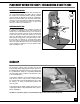
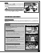
LOCK-OUT POWER SWITCH
ON/OFF SWITCH & SAFET
Y PIN
The ON/OFF switch assembly is equipped with a lock-
out safety pin . When the pin is installed through the
green “on” button , the machine cannot be started.
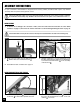
T
o start the machine, lift the red stop switch panel
and remove the lock-out pin. Lower the stop panel
and push the green “ON” button. Wait for the saw
blade to reach full speed before cutting.
T
o stop the machine, push on the RED “STOP” panel
and wait for the blade to come to a complete stop.
When you have finished using the machine be sure to
re-install the lock-out pin and unplug the machine
from the power source.
OFF
ON
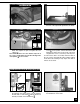
This model 90-320 is also equiped with a lock-out switch
.
When this switch is locked (OFF position), the machine
cannot be started by pressing on the green “on” but-
ton, even if the lock-out safety pin has been removed.
To start the machine, set the power lock-out switch to
ON position using the supplied key , then lift the red
stop switch panel and remove the lock-out pin.
Lower the stop panel and push the green “ON” button.
Set the lock-out switch to the OFF position and store
the keys in a safe place, out of the reach of children,
whenever the bandsaw is not in use.
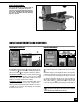
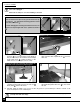
INSTALL THE FENCE ASSEMBLY
This model 90-320 M1 is equipped with an
Excalibur T-fence and guide rail system.
Follow all assembly and adjustment instruc-
tions in the 90-075B manual supplied in the
box with the Excalibur Universal Bandsaw
Rip Fence System.
15