
Use and Care Manual


WORKLIGHT
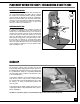
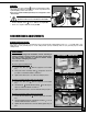
The goose neck style worklight on this model 90-320 provides
extra lighting
for added convenience. It can be repositionned for
optimal lighting of the work surface.
Note: Uses a standard 40 Watt (maximum) 120 volt appliance bulb
- Not Included.
To reduce the risk of fire, use 40 Watt (maximum) 120 volt
appliance bulb. Do not use standard household bulbs.
- Turn the ON/OFF switch once to turn the worklight ON:
- Turn it once again to turn the worklight OFF:
RECOMMENDED ADJUSTMENTS
REMOVING/INSTALLING THE BLADE
The 90-320 is designed to accommodate both wood and metal cutting blades from 1/8” – 1” in width and is sup-
plied with one 1/2” general purpose wood cutting blade (factory installed) and one 1/2” general purpose metal
cutting blade.
BL
ADE CLEARANCE
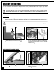
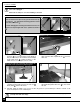
Note: When performing blade installation, removal, tensioning or
tracking, maximum clearance between the blade and both upper
and lower bearing assemblies is required to minimize friction,
which would be damaging to the blade.
Proceed as follows:
Mo
ve the upper assembly back:
1. Loosen the Allen bolt with the supplied 5 mm Allen
key.
2. Then pull on the assembly shaft going back as far as
possible for maximum blade clearance.
3. Tighten the Allen bolt to lock the assembly in place.
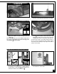
Mo
ve the lower thrust bearing away from the blade:
1. Loosen the Allen bolt with the supplied 5 mm Allen
key.
2. Turn the knob until the thrust bearing is as far as pos-
sible for maximum blade clearance.
3. Tighten the Allen bolt to lock the thrust bearing in place.
Mo
ve the lower blade guides away from the blade:
1. Loosen the two Allen bolts with the supplied 5 mm Allen
key.
2. Turn the adjustment knobs outward as needed
,
so as to
obtain
maximum blade clearance.
3. Tighten the two Allen bolts to lock the blade guides in posi-
tion.
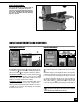
UPPER ASSEMBLY - RIGHT SIDE VIEW
TABLE UNDERSIDE - REAR VIEW
TABLE UNDERSIDE - FRONT VIEW
17