
Use and Care Manual


ADJUSTING THE UPPER / L
OWER BLADE GUIDES AND THRUST BEARINGS
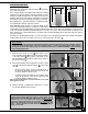
The blade guides keep the blade from moving from side to side during cutting and must be snug but not touching
the blade in order to ensure accurate cuts. The space between each guide and the blade must not exceed 0.02"
(the thickness of a sheet of paper). If less space is left, the blade will get stuck or jammed between both guides. Too
much friction will cause blade to overheat and break. Also, the guides must remain at least 1/32” behind the blade
teeth to prevent damage to the blade.
The thrust bearings keeps the blade from moving back and out of position when the work is being fed into the blade
and must be very close to the back of the blade to prevent damage to the blade during cutting.
Note: Before adjusting the upper and lower blade guides and thrust bearings, make sure the blade is tensioned and track-
ing properly. Adjust the upper and lower blade guides and thrust bearings after each blade tension and tracking adjust-
ment.
To avoid injury, make sure that both of the power switches are in the “OFF” position and that the power cord is
unplugged before performing any adjustments on the bandsaw.
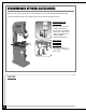
0.02"
0.02"
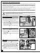
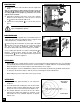
UPPER ASSEMBLY - RIGHT SIDE VIEW
Adjust the positioning of the upper blade guides and
thrust bearing assembly as follows:
The upper blade guides and thrust bearing are assem-
bled as one unit which can be moved back or forward.To
prevent damage to the blade, the blade guides must
remain behind the blade teeth during operation.
1. Loosen the Allen bolt with the supplied 5 mm Allen key.
2.
Move the upper assembly forward along the shaft ,
until the blade guides are at least 1/32" behind the
blade teeth , (do not protrude past the hollowed
part of the teeth of the blade.
3. Tighten the Allen bolt to lock the assembly in place.
1/32"
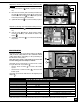
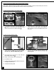
Adjust the positioning of the upper and lower blade
guides as follows:
1. Loosen the two Allen bolts with the supplied 5 mm
Allen key.
2. Turn the adjustment knobs inward as needed , to
obtain a space of 0.02" (the thickness of a sheet of
paper) between both guides and the blade .
Tip: Place a feeler gauge or sheet of paper between each
guide and the blade to make sure there is a
0.02" space.
3. Tighten the two Allen bolts to lock the blade guides
in position.
4. Repeat steps 1 to 3 with the lower blade guides .
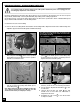
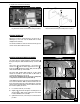
Adjust the positioning of the upper thrust bearing as follows:
1. Loosen the Allen bolt with the supplied 5 mm Allen
key.
2. Move the shaft in or out , until the thrust bearing
barely touches the blade (is 1/64" behind the back
of the blade ) .
3. Tighten the Allen bolt to lock the thrust bearing
in position.
1/64"
22