SIDEWINDER PULL AND ASSIST CAPSTAN WINCH OPERATION & MAINTENANCE 70605 – USA SIDEWINDER Copyright 2013 by General Machine Products Co., Inc QC Final Inspection by:_________________________ Date:__________________ Unit Serial Number:__________________ Build Date:__________________ All rights reserved. No part of this publication may be copied, reproduced or transmitted in any form whatsoever without the written permission of General Machine Products Co., Inc.
REVISION HISTORY: Rev No. Date Details Author 01 03-2006 Original issue A Miller 02 05-2007 US Version A Konschak 03 09-2009 Update manual to be consistent with others A Konschak 04 03-2010 Added figure 8 instruction and illustrations A Konschak 05 01-2014 Added new filter information A Konschak Page 2 of 24 General Machine Products Co., Inc.
CONTENTS 1.0 Introduction 2.0 Safety Instructions 3.0 General Description 4.0 Specification 5.0 Operating Procedure 6.0 Maintenance and Servicing 7.0 Towing Instructions 8.0 Equipment Layout 9.0 Spare Parts APPENDICES Appendix 1 Hydraulic Circuit Drawing Page 3 of 24 General Machine Products Co., Inc.
1.0 INTRODUCTION Founded by engineer George M. Pfundt in 1936, GMP started operations in a downtown Philadelphia building as a specialty machine shop doing work for the local Bell Telephone company and for the electric utility company. GMP expanded to a production shop after landing a contract with Western Electric Company and, subsequently, forming a close relationship with Bell Telephone Laboratories in Murray Hill, N.J.
2.0 SAFETY INSTRUCTIONS THIS EQUIPMENT MUST ONLY BE USED BY AUTHORIZED PERSONNEL, WHO HAVE BEEN SUITABLY TRAINED AND COMPETENT TO DO SO. THESE INSTRUCTIONS ARE TO BE MADE AVAILABLE TO OPERATORS OF THIS EQUIPMENT AT ALL TIMES, FAILURE TO OBSERVE THESE SAFETY INSTRUCTIONS COULD RESULT IN SERIOUS PERSONAL INJURY AND / OR PROPERTY DAMAGE. 1. Read and understand the operation and maintenance manual supplied with this equipment. Keep it in a convenient place for future reference. 2.
3.0 GENERAL DESCRIPTION The GMP SideWinder is a trailer mounted pull and assist capstan winch, mounted on a sturdy all-steel fabricated chassis. It is equipped with torsional suspension axles, stabilizing prop legs, a front telescopic jockey wheel and a tow bar with a Lunette Ring. The unit is easily pulled by a standard pickup truck. The power source is a gasoline engine which drives the fixed displacement tandem mounted hydraulic pumps.
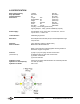
4.0 SPECIFICATION Max. Pulling Capacity Rope Speed Max. Capstan Diameter Dimensions: 1100 lbs (500 kg) 200 ft/min (60 m/min) 32” (813 mm) Length: 123” (3124 mm) Overall Width: 69” (1753 mm) Height: 57” (1450 mm) Weight: 1400 lbs. (635 kg) Track: 60” (1676 mm) Tire Size: F78-14 205/75D14 Coupling: Lunette Ring (Pintle hook) Lighting Adapter: 7-Way (others available by request) Power Supply: Honda GX390 13 HP, Recoil Start, Overhead Valve, Cast Iron Cylinder Sleeve, 1.
5.0 OPERATING PROCEDURE IT IS IMPERATIVE THAT ALL PERSONS USING, OPERATING OR MAINTAINING THIS WINCH BE FULLY TRAINED AND COMPETENT TO DO SO, AND HAVE READ THE ENTIRE OPERATING MANUAL. GMP CANNOT BE HELD RESPONSIBLE FOR MIS-USE OF THIS EQUIPMENT. 5.1 CONTROLS The operator controls have been designed to be safe and simple to use, with regard to ergonomic considerations. The operators control station is complete with the following: (see section 8) (a) Control lever for winching in and paying out.
5.3 PAYING OUT ROPE The rope take-up drum should be de-clutched by removing the lynch pin at the end of the drum shaft, grasping the drum flange, pulling and then rotating. Once the drum is free from its drive clutch, it is free to rotate on the shaft and the rope can be pulled manually from the drum. 5.4 STARTING THE ENGINE The engine manufacturer’s operating and service manual form an integral part of this manual.
5.5.2 Operate the drum control lever to engage the drum drive. This should be left in its operating position at all times that the winch is working. At all other times it is advantageous to return the drum control lever to its non-operating position. 5.5.3 Operate the winch control lever by pulling gently towards the operator. The rope will now be pulled in and be wound onto the rope take-up drum. The speed of pulling can be increased or decreased by adjusting the engine speed control.
5.6 REMOVING ROPE FROM SPLIT DRUMS The split drum has been designed to enable removal of the rope in a complete coil. In order to achieve this, ensure that the drum is fully engaged in its clutch and untie the rope from the drum. It is often advantageous at this stage to tie a few wraps of waste string, tie wraps or tape around the rope coils, ensuring that the string does not pass around one of the drum spokes. This will help to keep the rope in a nice tight coil when released from the drum.
6.0 MAINTENANCE AND SERVICING It is recommended that this winch is serviced every 12 months, regardless of its condition or the number of operating hours used. This will help to ensure reliable, trouble free service. It is imperative that any maintenance work is carried out by personnel suitably trained and qualified to do so. 6.1 PRE-WINCHING MAINTENANCE CHECK This should be carried out each day prior to the start of winching. 6.1.1 Check the hydraulic oil level.
6.2 MONTHLY MAINTENANCE This should be carried out at intervals not exceeding 4 weeks. These intervals will depend upon the degree of use of the winch. 6.2.1 Carry out all the pre-winching checks as detailed in 6.1 6.2.2 Check the function of all the lighting equipment, this should be more frequent if regular problems arise. 6.2.3 Check and adjust the tire pressures. 6.2.4 With the engine and drum shaft running, check the return filter condition indicator.
6.3 ANNUAL SERVICING This should be carried out at approximately 12 monthly intervals by a qualified and experienced workshop team. 6.3.1 Carry out all the work as specified above in section 6.2 6.3.2 Drain the hydraulic circuit of oil. Clean the filler/breather and replace. Renew the suction filter element and return line filter element. Refill with fresh oil. Check and reset all relief valves, (Refer to section 6.4 for further information). Refer to section 4 for grades of hydraulic oil. 6.5.
6.4 RELIEF VALVE SETTING Reference should be made to the hydraulic circuit diagram on page 19 of this manual. There are four relief valves in the circuit and with the exception of item 10, all have been factory pre-set and should not be adjusted. Item 10 is adjusted by the operator to set a maximum pulling tension. If it is necessary to replace or adjust any of the relief valves, the following guidance should assist. Item 7 This is a Capstan directional control valve.
7.0 TOWING INSTRUCTIONS BEFORE TOWING A. Check the load is distributed to give a positive hitch weight to ensure stable towing. Also ensure the hitch weight is within limit of the vehicle. B. Ensure that the Pintle hook is locked and the safety chains are securely attached to the tow vehicle. C. Make sure that the Jockey wheel is rotated up in the driving position and that the rear prop legs are securely retracted and locked. D. Make sure all trailer lights are working properly. E.
16 8.0 EQUIPMENT LAYOUT 1 6 10 12 11 13 5 7 14 2 8 9 3 15 4 1 2 3 4 5 6 7 8 9 10 11 12 13 14 15 16 CAPSTAN TOW BAR ROPE TAKE-UP DRUM JOCKEY WHEEL REAR PROP LEG CAPSTAN DRIVE GEARBOX ROPE TAKE-UP DRUM HYDRAULIC MOTOR ENGINE HYDRAULIC PUMPS HYDRAULIC OIL TANK HYDRAULIC OIL TANK FILLER / BREATHER RETURN LINE FILTER CONTROL PANEL REAR LIGHTING BOARD AXLE AND WHEELS CAPSTAN HYDRAULIC MOTOR Page 17 of 24 General Machine Products Co., Inc.
D A B C CAPSTAN WINCH CONTROL PANEL A. B. C. D. WINCH IN / PAYING OUT CONTROL LEVER ROPE TAKE-UP DRUM OPERATION CONTROL LEVER TENSION CONTROL KNOB PRESSURE GAUGE / TENSION INDICATOR HYDRAULIC OIL TANK SUCTION FILTER Page 18 of 24 General Machine Products Co., Inc.
9.0 USER REPLACEABLE PARTS Return Line Filter Element Replacement Replace the Return Line Filter Element when the arrow of the clogging indicator is in the red range. Indicator showing need for filter element replacement. 1. Unscrew the return line filter top cap using a suitable wrench. 2. Remove the clogged element and plastic carrier. Twist and pull the element to separate it from the carrier. Install new element in carrier and drop in filter housing.
Hydraulic Circuit Drawing Page 20 of 24 General Machine Products Co., Inc.
GMP LIMITED WARRANTY 1a. General Machine Products Co., Inc. ("GMP") warrants to the purchaser and/or end user: (1) that a new product sold and manufactured by GMP will be free from original defects in material and workmanship for one year from the date the product was delivered to the purchaser and/or end user, or for the lifetime of the Modular Plug Presser; (2) that a new product sold and not manufactured by GMP will be covered exclusively by the manufacturer's warranty.
labor, transportation, tolls, lodging and meals at a location remote from its prime facility, or to demount our product or part from its remote location and forward to its prime facility, are not the responsibility of GMP, and are not covered by this Warranty. 3f.
Page 23 of 24 General Machine Products Co., Inc.
GMP • 3111 Old Lincoln Hwy • Trevose, PA 19053 • USA TEL: +1-215-357-5500 • FAX: +1-215-357-6216 • EMAIL: info@gmptools.com Page 24 of 24 General Machine Products Co., Inc.