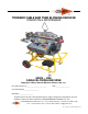
TORNADO CABLE AND TUBE BLOWING MACHINE OPERATION & MAINTENANCE 89000 – USA CABLE BLOWING MACHINE Copyright 2009 by General Machine Products Co., Inc. QC Final Inspection by:_________________________ Date:__________________ Unit Serial Number:__________________ Build Date:__________________ All rights reserved. No part of this publication may be copied, reproduced or transmitted in any form whatsoever without the written permission of General Machine Products Co., Inc. General Machine Products Co., Inc.
REVISION HISTORY: Rev No Date Details Author 01 01-2006 Original issue A. Miller 02 02-2006 Programming Instructions Updated A. Sibun 03 07-2006 New photo with air inlet pipe added A. Crawford 04 12-2006 Cable seal, collets and plug selection chart updated A. Miller 05 02-2007. Recommended spares list revised A. Crawford 06 01-2008 Programming Instructions Updated A. Sibun 07 03-2008 Programming Instructions Updated A. Sibun 08 11-2009 US GMP Version 1 A.
CONTENTS 1. Safety Instructions 2. Critical Points 3. General Description 4. Specification 5. Operating Procedure - Sub-Duct Integrity and Lubrication 6. Operating Procedure—Cable Blowing 7. Maintenance 8. Procedure for Replacement of Chain Drives 9. Procedure for Replacement of Cable Collets 10. Procedure for Replacement of Sub-Duct Clamp Collets 11. Procedure for Replacement of Cable Seals 12. Procedure for Adjusting the Air Chamber and collet type cable infeed guide assembly height 13.
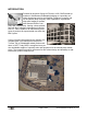
INTRODUCTION Founded by engineer George M. Pfundt in 1936, GMP started operations in a downtown Philadelphia building as a specialty machine shop doing work for the local Bell Telephone company and for the electric utility company. GMP expanded to a production shop after landing a contract with Western Electric Company and, subsequently, forming a close relationship with Bell Telephone Laboratories in Murray Hill, N.J.
1. SAFETY INSTRUCTIONS This equipment must only be used by authorized personnel who have been suitably trained and competent to do so. These instructions are to be made available to operators of this equipment at all times. Failure to observe these safety instructions could result in serious personal injury and or property damage. WORK AREA AND GENERAL SAFETY 1) Read and understand the operation and maintenance manual supplied with this equipment. Keep it in a convenient place for future reference.
16) Waste hydraulic oils are to be disposed of via an environmentally acceptable method. 17) Wear ear defenders if noise levels are considered high to prevent ear damage. 18) Machine may cause additional fire hazard if involved in an existing fire due to compressed air and hydraulic oils. 19) No personnel are to be in manholes or ducts when the Cable Blowing Machine is being operated. 20) The machine must be operated on firm ground. 21) Stay clear of cables or lines under tension.
GENERAL HYDRAULICS SAFETY INSTRUCTIONS Escaping fluids under pressure can penetrate the skin and cause serious personal injury. Observe the following precautions to avoid hydraulic hazards: 1) Ensure all hydraulic connections are securely tightened before operating the machine. 2) Check for leaks with a piece of cardboard. Do not use your hands! 3) Do not exceed working pressure of hydraulic hoses. 4) Visually inspect hoses regularly and replace if damaged.
2. CRITICAL POINTS THAT DRAMATICALLY AFFECT THE OPERATION OF THE CABLE BLOWING MACHINE ▪ ▪ ▪ ▪ ▪ ▪ ▪ ▪ ▪ ▪ ▪ ▪ ▪ ▪ ▪ ▪ ▪ One (1) turn on the cable clamping screw Tractor drive to be closed at all times when cable is installed into machine. Air Chamber height adjustment correctly set. Cable infeed bracket height adjustment correctly set. Cord seals in air chamber correctly fitted to provide good sealing. Correct cable seals fitted. Sub-duct fully connected and pressure tested.
DISCLAIMER GMP and CBS Products takes care in the design of its products to ensure that the cable is protected during installation. Due to the variety and different methods of cable manufacture the responsibility of checking the cable compatibility with the equipment lies with the operator. Therefore, GMP and CBS Products cannot accept liability for any damage to the cable. Page 9 of 64 General Machine Products Co., Inc.
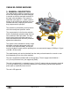
CABLE BLOWING MACHINE 3. GENERAL DESCRIPTION The cable blowing machine comprising of an air box and cable pusher has been designed to provide an effective and safe method of fiber optic cable installation. The system installs fiber optic cable of 6 - 32mm overall diameter at up to 260 ft/min (80m/min) into preinstalled sub-ducts, employing the viscous drag compressed air principle. The machine is protected by preset pressure relief valve and preset pressure sensor.
FEATURES Fully labeled control panel containing: • Power ON/OFF button (silver) • Emergency Stop Button (red) • Blowing speed read out in either ft/min or m/min through a separate calibration • Length counter recording in feet or meters through a separate calibration • Hydraulic pressure read out dial • Air pressure read out dial • Air pressure control lever • Hydraulic on/off control valve • Emergency stop connection socket • Adjustable speed control for drive belts • Battery Charging Connection Control pa
4. SPECIFICATION Serial No.
ELECTRONIC CONTROL SYSTEM Power Requirements: 12 Volts DC ( gel cell battery supplied) Fuse Rating: 3.15 amp (slow-blow) DIMENSION AND WEIGHTS Height: 48 1/2” (1230mm) Length: 42” (1060mm) Width: 27 1/2” (700mm) Weight: 155 lbs. (70kg) Tire Size: 3.00 - 4 / 260 x 85 Tire Pressure: 25 psi (1.
5. OPERATING PROCEDURE SUB-DUCT INTEGRITY AND LUBRICATION Sub-duct integrity and lubrication is entirely the responsibility of the operator. 1. Ensure that the sub-duct is fully prepared for use i.e.: Fully connected Pressure tested Cable exit retaining device fitted lubricated (if required) VERIFYING AIR FLOW AND LUBRICATION (IF REQUIRED) 2.
5. Fit the cable seal plug and two cable seals (coated with silicon grease) into the lower half cable seal collet. Ensure that the split of the innermost seal is in the lower half of the air chamber slightly rotated from the vertical. The split of the outer most seal is also in the lower half of the air chamber slightly rotated from the vertical in the other direction to the innermost seal. Both grooves face away from the tractor drive. 6.
9. Notify installation team that preparations are competed and that checking the air flow through the sub-duct is about to commence. 10. Note: Only authorized fully trained operators should be allowed to operate the air compressor. With the air compressor ready to provide air, turn the air valve to the “open” position. 11. Confirm that air is being expelled from the far end of the sub-duct under pressure.
12. Ensure all air has exhausted from the air chamber and sub-duct. Open the air chamber and sub-duct clamp and withdraw the sub-duct. Add GMP’s AirGlide lubricant to the sub-duct at the rate of 1 quart (.95 liters) of lubricant per 2000 ft (600 m) of sub-duct assuming a 1 1/4 bore. Adjust quantity for different bore sizes. Note: Never open the air chamber until the air pressure gauge reads zero. 13.
15. NOTIFY INSTALLATION TEAM Notify installation team that preparations for lubricating the sub-duct are complete and ready to commence. 16. With the compressor ready to provide air, turn the air valve to the open position. 17. When the foam plug has been expelled from the end or the sub-duct, turn the air valve to the “closed” position and shut down the compressor. Allow the air chamber and sub-duct to exhaust all the compressed air.
6. OPERATING PROCEDURE CABLE BLOWING It is imperative that all persons using, operating or maintaining this cable blowing machine be fully trained and competent and authorized to do so and have read the entire operation manual. General Machine Products Co., Inc. and CBS Products Ltd, CANNOT BE HELD RESPONSIBLE FOR MISUSE OF THIS EQUIPMENT. 1. Position the Cable Blowing Machine in line with the proposed sub-duct. 2.
8. Unscrew the sub-duct clamp retaining bolts. Refer to the Section 4 “SPECIFICATION” for the correct pressure settings for the relief valve and pressure switch and to Section 6 “MAINTENANCE” for the setting procedures. NOTE: The cable blowing machine is supplied as standard with the pressure relief valve set at 1600 psi (110 Bar) and the pressure switch set at 1450 psi (100 Bar), these settings are suitable for cables in the range 12 - 32mm O.D. For cables 6 - 12mm O.D.
12. Release the adjusting screw locking ring, turn the adjusting knob until the mark on the air chamber support bracket aligns with the size of the cable to be installed on the increment gauge. Tighten the locking ring to prevent any movement during installation. (Refer to section 11 for details). 13. Ensure that the sub-duct is fully prepared for use, i.e.
15. Select the correct size cable infeed collet to suit the size of the cable to be installed and secure with the cap screw into each housing. Note: Sealing cord is not required on this collet. Always check and verify the correct size collets are fitted before operating the blowing machine. 16. Adjust the height of the intake cable guide bracket to suit the size of the collet and the size of the cable to be installed.
Close the infeed cable guide upper housing and secure with the swing bolt and thumb nut, ensure the cable is correctly located in the bore of the collet. Note: Ensure that the compressor air supply is never allowed to enter the air chamber or subduct when the top tractor drive frame is in the upper position. (i.e. not clamping the cable) and / or the infeed guide bracket is open or not correctly secured.
21. Install the second seal into the outer groove with the seal split in the lower half of the air chamber rotated slightly to the other side of the vertical (compared to the first cable seal). Ensure the groove seal lip is away from the tractor drive facing the sub-duct. 22. Fit the upper cable guide collet in po- 23. Re-fit the air chamber lid ensuring corsition ensuring both seals are located rect location on the dowels and tighten correctly. down the 4 retaining knobs. ENSURE THAT: 24.
26. The emergency stop button is set. (i.e. in upper position). If not set, twist counter-clockwise to reset. 27. Connect the two hydraulic hoses and the emergency stop cable from the power pack (or hydraulic power source). Never run the blowing machine without the emergency stop cable being connected. NOTE: Only authorized, fully trained operators should be allowed to operate the hydraulic power pack (or hydraulic power source). 28.
31. Turn hydraulic valve to “ON” position. 32. Ensure the emergency stop button is in the reset position. (Twist counterclockwise to reset). 33. Press the on/off button. Note: Do not press the RST Button while powering up the counter. The display will indicate the speed and distance travelled by the cable. To toggle between speed and distance press the SEL (green) button. R displayed on the left side of the screen designates speed (rate). To reset the distance press RST (red) button.
35. Continue to install cable into sub-duct. The operator wearing work gloves should hand guide the cable into the blowing machine through a dry clean cloth to prevent any debris on the cable entering the blowing machine and to ensure the cable enters the machine inline with the tractor drive belt without and bending or deviation. Note: Care must be taken to avoid injury by clothing or fingers being dragged into the machine. Failure to do so will result personal injury. 36. When approximately (650 ft.
40. IF THE BLOWING MACHINE STOPS SUDDENLY If the cable blowing machine stops suddenly during the blowing operation it is likely that the pressure switch has tripped stopping the power pack because: A) The cable has reached its destination and the cable exit retaining device has stopped the travel of the cable. B) The cable has become jammed, has hit an obstruction in the duct or the cable blowing operation has reached its maximum capability.
IN THE EVENT OF AN EMERGENCY Push the emergency stop push button. Turn the hydraulic valve to the “off” position. Turn the speed control knob to “MIN” position Press the on/off button to turn the electric’s (fully counter clockwise) off. Turn off the air supply (if required). Correct the problem that caused it to stop. Page 29 of 64 General Machine Products Co., Inc.
TO RESTART 1. Ensure the power pack is running 2. Turn the hydraulic valve to the “on” position. 3. Press the power on/off button 4. Turn the air valve to the open position (assuming the required amount of cable in in the duct) 5. Turn the speed control valve towards “MAX” until the required speed is achieved Page 30 of 64 General Machine Products Co., Inc.
7. MAINTENANCE To ensure reliable service from your Cable Blowing Machine, we recommend the unit be completely serviced every 6 months AIR CHAMBER The air chamber should be inspected after each operation for seal damage or wear. Seal cord should be replaced if damaged or missing and secured in position with the adhesive provided. The cable seals should be checked for damage or wear and replaced with new ones if required.
GENERAL The machine should be stored under cover when not in use. The machine should be wiped clean after each time used. ALWAYS ensure that there are sufficient cable seals, cord seal, cord adhesive and silicone grease available in the toolbox to cover the next installation. ALWAYS ensure that the battery is fully charged, before the cable blowing machine is to be used. Note: The battery is not charged by the power pack.
PROCEDURE FOR SETTING THE RELIEF VALVE AND PRESSURE SWITCH FOR CABLE SIZES 6-12 OD When installing small diameter cables with “soft/flexible” characteristics, it will be necessary to reduce the pressure relief valve and pressure switch settings to prevent the cable buckling or being jammed in the air chamber mounted collet. The pressure relief valve should be set to 1015 psi (70 Bar).
TO SET PRESSURE SWITCH SMALL DIAMETER (UNDER 12MM) OR FLEXIBLE CABLE Clamp a piece of 1” O.D. dowel/round bar x 13” long between top and bottom housings so it butts up to the air chamber mounted collets (in effect placing the motors in stall mode). 1. 2. 3. 4. Connect the electric lead to the power pack and blowing machine. Rotate the speed control knob fully counter-clockwise to “MIN”. Press the on/off button (to turn the electric’s on).
7.1.
7.2. TYPICAL PROBLEMS EXPERIENCED WHEN CABLE BLOWING: PROBLEM SOLUTION Tractor feed does not pull the cable off the Assist the drum by turning it or pulling the cable off the drum by hand. drum The Cable Blowing Machine stops. Hydraulic pressure gauge reads zero. Machine has tripped out on pressure switch, cable has hit an obstruction or become jammed. Turn hydraulic valve to off position. Turn speed control knob to “MIN”. If cable is jammed try restarting the Cable Blowing Machine.
7.3. BASIC TOOL KIT SUPPLIED WITH CABLE BLOWING MACHINE: PART No.
8. PROCEDURE FOR REPLACEMENT OF CHAIN DRIVES Tools required: 6mm Allen Key 13mm Wrench Ensure the hydraulic hoses to the power pack are disconnected from the blowing machine before carrying out this procedure. 1. Remove the hydraulic motor from the top 2. Remove the stop washer on the bottom of frame using 6mm Allen Key. Do not discon- the main jacking screw using a 6 mm Allen nect hydraulic hoses connected to the motor. key. 3.
7. Remove the tension sprocket assembly 8. Remove the chain-connecting link. 9. Remove the chain. 10. Check the chain support slide bars for wear. Clean and relubricate. 11. Pass the pre-lubricated new chain around the drive sprocket. Feed the chain along the unit and reconnect the chainconnecting link. Remember to install the 2 center connecting link plates. 12. Align the tension sprocket with the chain and locate into position. Insert the tension pin through the tension sprocket.
Reassembling the top and the bottom parts of the pusher unit.▪ ▪ Refit the main clamping screw. ▪ Replace the stop washer on the bottom of the main jacking screw using a 6mm Allen key. ▪ Replace the hydraulic motor using the 6mm Allen key. Adjust top chain, do not over tighten chain. Page 40 of 64 General Machine Products Co., Inc.
9. PROCEDURE FOR REPLACEMENT OF CABLE COLLETS Ensure the air supply is disconnected from the blowing machine before carrying out this procedure. Tools Required 4mm Allen Key Step 1 Collet Removal ▪ Ensure that the air valve is closed and the air pressure is at zero. ▪ Open the air chamber to expose the collets.
10. PROCEDURE FOR REPLACEMENT OF SUB-DUCT COLLETS Ensure the air supply is disconnected from the blowing machine before carrying out this procedure. Always check and verify the correct size collets are fitted before operating the blowing machine. SUB-DUCT CLAMP COLLETS Tools Required 4mm Allen Key Step 1 Collet Removal Open the sub-duct clamp. Remove the socket head cap screws (2) using a 4mm Allen key and remove the collet (2).
11. PROCEDURE FOR REPLACEMENT OF CABLE SEALS Ensure the air supply is disconnected from the blowing machine before carrying out this procedure. Always check and verify the correct size collets are fitted before operating the blowing machine. Tools Required No tools are required. Step 1 Seal Removal / Refitting Ensure that the air valve is closed and that the air pressure gauge is at zero. Open the air chamber to expose the cable seals. Remove the seals. Refit the required seals.
12. PROCEDURE FOR THE AIR CHAMBER AND COLLET TYPE CABLE INFEED CABLE GUIDE ASSEMBLY HEIGHT Step 1 When changing collets and seals to accept smaller / larger sizes of cable it is necessary to adjust the height of the air chamber and the collet type infeed guide assembly. This setting must be carried out accurately, as failure to do so will seriously impair the function of the machine.
13. ALIGNMENT OF AIR CHAMBER TO THE CABLE PUSHER UNIT 1. Insert a round parallel bar between the top and bottom cable pusher housings and clamp down. Ensure the rod doesn't interfere with metering wheel and that it passes through he air chamber. (See picture). 2. Refer to Section 11.0 Procedure for adjusting the air chamber and infeed guide assembly height and the height of the air chamber. Adjust the air chamber such that the top face of the lower housing is inline with the centre line of the rod. 3.
14. MONTHLY SERVICE – CHECK LIST 1. Remove the drive chains from the pusher unit. Check both of the chains for excessive wear. Replace, if required and lubricate with the spray grease provided. 2. Remove any debris from the housings. 3. Check the chain supports slide bars for excessive wear and lubricate with the spray grease provided. Replace, if required. 4. Check all other moving parts e.g. bearings, shafts, sprockets etc. . and lubricate. 5. Check main jacking screw . and lubricate. 6.
15. SERVICE HISTORY RECORD Service no Date Carried out by Page 47 of 64 Record of service/repair General Machine Products Co., Inc.
16. TROUBLESHOOTING GUIDE Initial starting hydraulic pressure at the point of starting a cable installation the hydraulic pressure must be between 290 - 580 psi (20-40 bar). If not, do not continue. See the below sections “Will Not Achieve Max Pressure” and “Runs At Higher Than Expected Pressure” to rectify the problem before commencing cable installation.
EXCESSIVE AIR LEAKAGE FROM AIR CHAMBER • Damaged cord seal • Cable seals worn, incorrect size, wrong way round, misalignment of air chamber bracket in relation to cable diameter • Incorrect collets COUNTER NOT READING OR GIVING INCORRECT READINGS • Battery low on power • Counter program has been changed - clear program and re-program as described on page 60 Page 49 of 64 General Machine Products Co., Inc.
17. RECOMMENDED SPARE PARTS Part No Description Qty Required 89155 Chain ½ Duplex (Black red) 2 89158 Motor (32 cc/rev) 2 31552 Seal Cord (Cut to length as required) 30 ft. 89148 Silicon Grease 1 Tube 89149 Sealing Cord Glue 1 Tube 89156 Wheel . Ref. 260 (Pneumatic) 2 89151 Wheel . Ref. PBW280-2 (Solid) 2 31727 Chain Support Slide Bar 2 89153 F Metaflux chain spray 70-88 1 32512 Battery 12 VDC lead acid battery 1 Page 50 of 64 General Machine Products Co., Inc.
Appendix 1 LAYOUT OF CABLE BLOWING MACHINE 5 1 2 10 15 3 4 8 9 6 7 14 11 13 16 12 1 Cable Pusher 2 Air Chamber 3 Sub-Duct Clamp 4 Cable infeed bracket assembly 5 Unit Lifting Point 6 Hydraulic Control Panel 7 Electronic Control Panel 8 Air “Open / Close” Valve 9 Air Hose Connection 10 Hydraulic Hose Connection (at rear of unit) 11 Emergency stop socket (on side of unit) 12 Frame Leveling Foot 13 Tool Box 14 Mounting Frame 15 Tractor Drive Movement Indicator 16 12 Volt Battery Access door (under un
Appendix 2 Page 52 of 64 General Machine Products Co., Inc.
Appendix 3 CABLE BLOWING MACHINE SERVICE CONNECTIONS Compressed Air Hose Connected to Cable Blowing Machine Hydraulic Hose Connections Power Pack to Cable Blowing Machine Air Compressor Sub Duct Power Pack Cable Blowing Machine Emergency Stop Cable Power Pack to Cable Blowing Machine Fiber Optic Cable Cable Drum Page 53 of 64 General Machine Products Co., Inc.
Appendix 4 HYDRAULIC AND ELECTRONIC CONTROL PANEL LAYOUT 3 4 1 7 6 2 8 5 9 1 Air Pressure Gauge 2 Hydraulic Pressure Gauge 3 Speed Control Knob 4 Hydraulic “On / Off” Lever 5 Power “On / Off” Button 6 Emergency Stop Button 7 Length / Speed Digital Display 8 Hydraulic Control Panel 9 Electronic Control Panel Page 54 of 64 General Machine Products Co., Inc.
Tornado Configuration Guide Appendix 5 Let our "Cable Blowing Experts" tailor your configuration. Please don't hesitate to call our Hotline at 1-800-345-6009 for any questions you may have.
Notes: Page 56 of 64 General Machine Products Co., Inc.
Appendix 6 Programming Parameters for CUB5R Counter/rate Meter Serial Numbers 0315 Onwards The device must be wired and installed into the machine prior to programming. Tornado is fitted with C-M-DEV-CUB5R, reflective version The DIP switch positions are as follows: 1 OFF 2 OFF 3 OFF 4 OFF Please see the attached CUB5 Programming Overview attached to this document.
First reset the current settings to Factory Settings on the counter: Scroll to 3-DSPLAY Skip through the parameters until FACT SET is displayed. Change this to YES by pressing RST PRO NO should be displayed, Press SEL. Continue to re-program the Counter by pressing and holding SEL to re-enter programming mode. Pro-no will be displayed, press RST to move through the relevant sections.
CUB5 PROGRAMMING QUICK OVERVIEW Page 59 of 64 General Machine Products Co., Inc.
GMP Limited Warranty 1a. General Machine Products Co., Inc. ("GMP") warrants to the purchaser and/or end user: (1) that a new product sold and manufactured by GMP will be free from original defects in material and workmanship for one year from the date the product was delivered to the purchaser and/or end user, or for the lifetime of the Modular Plug Presser; (2) that a new product sold and not manufactured by GMP will be covered exclusively by the manufacturer's warranty.
4a. GMP products or parts which become part of a total assembly which has been designated and/or manufactured by others, are not covered by this Warranty unless GMP reviews the total assembly and expressly extends its warranty. 4b. Design, material and workmanship furnished by others to install or operate a GMP product or part are not covered by this Warranty with respect to GMP's products or parts which are used in that particular assembly. 4c.
GMP • 3111 Old Lincoln Hwy • Trevose, PA 19053 • USA TEL: +1-215-357-5500 • FAX: +1-215-357-6216 • EMAIL: info@gmptools.com Page 62 of 64 General Machine Products Co., Inc.