
Manual

Page 10 of 64 General Machine Products Co., Inc.
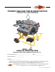
CABLE BLOWING MACHINE
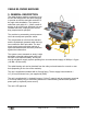
3. GENERAL DESCRIPTION
The cable blowing machine comprising of an
air box and cable pusher has been designed
to provide an effective and safe method of fi-
ber optic cable installation. The system in-
stalls fiber optic cable of 6 - 32mm overall di-
ameter at up to 260 ft/min (80m/min) into pre-
installed sub-ducts, employing the viscous
drag compressed air principle.
The machine is protected by preset pressure
relief valve and preset pressure sensor.
The compressed air is fed into the sub-duct,
and the hydraulically powered cable feed sys-
tem controls the fiber optic cable. The elec-
tronic control system provides read out of
speed and distance and automatic protection
against duct obstruction.
The system comes mounted on sturdy, height
adjustable, wheeled tubular steel trolley unit
for ease of site maneuverability, and is pow-
ered by a hydraulic supply system operating from a recommended supply of 2000 psi x 5 gpm
(140 Bar x 20 liters/min).
The cable-blowing unit can be detached from the trolley unit and located in a trench or man-
hole (depending on the size of the manhole).
The unit is supplied as standard with a Chicago fitting. The air supply hose should be 1
1/4” (32 mm) minimum bore, (not supplied by GMP).
The unit is supplied with 2 x hydraulic hoses x 23 feet (7 meters) and an emergency stop lead
x 26 foot (8 meters) long for connecting between the cable blowing machine and hydraulic
power pack (or hydraulic power source).
The unit is CE approved.