
Manual


Page 51 of 64 General Machine Products Co., Inc.
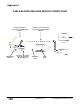
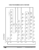
LAYOUT OF CABLE BLOWING MACHINE
1 Cable Pusher
2 Air Chamber
3 Sub-Duct Clamp
4 Cable infeed bracket assembly
5 Unit Lifting Point
6 Hydraulic Control Panel
7 Electronic Control Panel
8 Air “Open / Close” Valve
9 Air Hose Connection
10 Hydraulic Hose Connection (at rear of unit)
11 Emergency stop socket (on side of unit)
12 Frame Leveling Foot
13 Tool Box
14 Mounting Frame
15 Tractor Drive Movement Indicator
16 12 Volt Battery Access door (under unit)
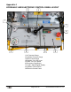
Appendix 1
14
9
6
13
8
3
2
15
1
5
10
7
11
4
12
16