CABLE FLEETER Operation and Maintenance Model 89016 All rights reserved. No part of this publication may be copied, reproduced or transmitted in any form whatsoever without the written permission of General Machine Products Co., Inc. General Machine Products Co., Inc. • 3111 Old Lincoln Hwy • Trevose, PA 19053 • USA TEL: +1-215-357-5500 • FAX: +1-215-357-6216 • WEB: www.gmptools.
INDEX 1.0 Introduction and Safety Instructions 2.0 General Description 3.0 Cable Threading and Operating Procedure 4.
SAFETY INSTRUCTIONS THIS EQUIPMENT MUST ONLY BE USED BY AUTHORIZED PERSONNEL, WHO HAVE BEEN SUITABLY TRAINED AND COMPETENT TO DO SO! THESE INSTRUCTIONS ARE TO BE MADE AVAILABLE TO OPERATORS OF THIS EQUIPMENT AT ALL TIMES. 1. Read and understand the operation and maintenance manual supplied with this equipment. Keep it in a convenient place for future reference. 2. Keep children and untrained personnel away from this equipment while in operation. 3. Keep all guards and safety devices in place.
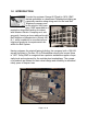
1.0 INTRODUCTION Founded by engineer George M. Pfundt in 1936, GMP started operations in a downtown Philadelphia building as a specialty machine shop doing work for the local Bell Telephone company and for the electric utility company. GMP expanded to a production shop after landing a contract with Western Electric Company and, subsequently, forming a close relationship with Bell Telephone Laboratories in Murray Hill, N.J.
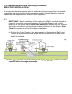
2.0 General Description The GMP Cable Fleeter has been developed to enable longer lengths of fiber optical cable to be laid from a single drum. With the increasing trend of longer cable installations with either GMP’s SideWinder (P/N 70605) winching system or GMP’s Tornado Cable Blowing Machine (P/N 89000), there is a need for a cable fleeter. The need arises following the initial installation of the first half of the fiber optic cable from the drum.
WARNING The principle of operation and storage rate has been designed for major cable types. However, account should be made for miscellaneous cables, which have characteristics that do not always meet this standard. This may affect the volume of cable stored or the machine may have to be run at lower speeds. This could be curved cables, extremely soft cables or non-symmetrical cables. The operator must establish the correct speed of operation and loading for the cable types being employed.
3.0 Cable Installation and Operating Procedure MID POINT INSTALLATION It is important that all personnel using or maintaining this equipment be fully trained, competent and have read the entire operating manual. General Machine Products cannot be held responsible for misuse of this equipment. 3.
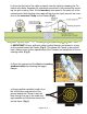
b) Once the first half of the cable is placed, free the cable by releasing the Tornado’s drive belts. Separate the innerducts connected in the manhole by removing the split coupling. Next, lift the Innerduct (connected to Tornado) out of the manhole and (while feeding extra cable off the drum by hand) connect the innerduct to the Innerduct Clamp on the Fleeter (Fig 2). Fig 2 c) IMPORTANT! Ensure sufficient cable is pulled through and placed in a loop on the ground beside the Fleeter (Fig 2).
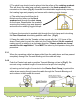
f) The cable loop should now be placed into the rollers of the rotating quadrant. This will direct the cable loop vertically upwards to the fixed quadrant roller mounted on the frame (Fig 4). Assemble the detachable segments by ensuring the locating lugs seat properly and secure with retaining toggle clamps. g) The cable loop should then be directed over the rollers on the fixed quadrant and through the duct clamp on the frame.
At the end of the cable installation open both the Rotating and Fixed Quadrants to allow complete removal of the cable from the Fleeting Basket. It will be necessary to cut and remove innerduct from the cable using a GMP Duct Slitter (GMP P/N 10923) or Cordless Duct Saw (GMP P/N 70427). A small loop of cable will remain which should be looped and placed in the manhole.
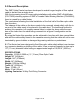
4.0 Trailer Chassis The trailer unit is fitted with towing equipment to comply with D.O.T. Standards. The towing bracket has hand operated adjustable height jockey wheel . 4.1 Maintenance The tire pressure should be checked daily and should be set at 35 psi (2.4 bar). Cable Storage Cassette This assembly will not require any maintenance. Make sure it is kept free of materials which may cause damage to fiber cables during operation.
4.2 Towing Instructions Before Towing a. Check the ball head cup is well greased. b. Raise the coupling above height of the ball by use of jockey wheel provided. c. Reverse towing vehicle until ball is directly below the coupling. d. Grasp locking lever on top of coupling and lift up while pressing the trigger. Wind up jockey wheel (thereby lowering the trailer) until ball on towing vehicle enters ball cup on coupling. Continue winding up jockey wheel until the ball is firmly seated in the ball cup.
Servicing a. Apply grease to ball and to cup of ball head after cleaning each item. (Alternatively towing eye and jaw are fitted). This to be carried out each time the trailer is to be towed. b. Oil all moving parts weekly having wiped away all corrosion and dirt deposits. 4.3 Spare Parts For spare parts contact: General Machine Products Co., Inc.
Page 14 of 16
Page 15 of 16
GMP • 3111 Old Lincoln Hwy • Trevose, PA 19053 • USA TEL: +1-215-357-5500 • FAX: +1-215-357-6216 • Web: www.gmptools.