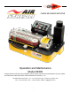
CABLE BLOWING MACHINE Operation and Maintenance Model 89300 All rights reserved. No part of this publication may be copied, reproduced or transmitted in any form whatsoever without the written permission of General Machine Products Co., Inc. General Machine Products Co., Inc. • 3111 Old Lincoln Hwy • Trevose, PA 19053 • USA TEL: +1-215-357-5500 • FAX: +1-215-357-6216 • EMAIL: info@gmptools.
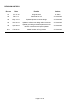
REVISION HISTORY: Rev.no Date Details Author 01 Jul -27-10 Original issue A. Sibun 02 Feb-1-11 Reformat for US A. Konschak 03 May -19-11 Updated photos to newer design A. Konschak 04 Nov-20-12 Update to reflect new design without remote A. Konschak 05 April-09-13 Update grounding and belt replacement info Various corrections and spec updates A. Konschak 05.1 Feb-28-14 Added location of long inserts A.
CONTENTS 1. Safety Instructions 2. Critical Points 3. General Description 4. Specification 5. Operating procedures 6. Maintenance 7. Procedure for changing inserts in the tube clamp 8. Procedure for changing inserts in the air box 9. Procedure for changing inserts in the infeed and exit guides 10. Procedure for replacing the air box housing seal 11. Procedure for changing the air box infeed guide 12. Procedure for changing the cable drive belts 13. Procedure for tensioning the drive belts 14.
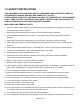
1.0 SAFETY INSTRUCTIONS THIS EQUIPMENT SHOULD BE USED ONLY BY PERSONNEL WHO HAVE BEEN GIVEN THE APPROPRIATE TRAINING, AND WHO ARE COMPETENT TO USE IT. THESE INSTRUCTIONS ARE TO BE MADE AVAILABLE TO OPERATORS OF THIS EQUIPMENT AT ALL TIMES, FAILURE TO OBSERVE THESE SAFETY INSTRUCTIONS COULD RESULT IN SERIOUS PERSONAL INJURY AND/OR PROPERTY DAMAGE. WORK AREA AND GENERAL SAFETY 1. Read and understand the operation and maintenance manual supplied with this equipment.
been closed on to the cable. Do not turn the air on until a reasonable length of cable 150 ft. (50m) has been installed into the tube. 23. Ensure the cable drum rotates freely on its stand, the cable should leave from the top of the drum. 24. The cable should enter the machine in a clean and dry condition. In damp, dusty atmospheres, the cable should be cleaned continuously as it enters the machine.
GENERAL PNEUMATIC SAFETY INSTRUCTIONS The GMP Fiber Optic Cable Blowing Machine is a pneumatic device, using pressurized air to project cable at high velocities. Please observe the following precautions when operating the Cable Blowing Machine: ► Compressed air can cause flying debris. This could cause personal injury. Always wear personal protective equipment. ► Ensure no personnel are in the manhole at the far end of the cable run. Severe personal injury may result.
2.0 CRITICAL POINTS THAT DRAMATICALLY AFFECT THE OPERATION OF THE CABLE BLOWING MACHINE ► PRESSURE ON THE CABLE (POSITION OF THE CLOSE ARM ASSY) SHOULD BE SET AS PER THE INSTRUCTIONS ► BELTS TO BE CLOSED AT ALL TIMES WHEN CABLE IS INSTALLED INTO MACHINE. ► CORD SEALS IN AIR CHAMBER IN GOOD CONDITION AND CORRECTLY INSTALLED TO PROVIDE GOOD SEALING. ► CORRECT CABLE SEAL INSTALLED. ► TUBE FULLY CONNECTED AND PRESSURE-TESTED.
DISCLAIMER General Machine Products Co., Inc. takes care in the design of its products to insure that the cable is protected during installation. Due to the variety and different methods of cable manufacture the responsibility of checking the cable compatibility with the equipment lies with the operator. Therefore, General Machine Products cannot accept liability for any damage to the cable.
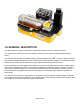
3.0 GENERAL DESCRIPTION The GMP AirStream machine is designed to install small diameter cable into underground tubes. The machine uses a DC servo motor and reduction gearing to drive a pair of flexible belts (both belts are driven). The belts are covered with a soft pliable coating to prevent damage to the cable. A range of different coatings and profiles are available depending on the surface texture of the cable being installed.
4.0 SPECIFICATION Cable size: 2.5 to Tube size: (OD) 5 to 11.0mm 18.0mm 0.118” to 0.433” 0.197” to 0.708” Cable speed: 0-80m/min. 0-262 ft/min Maximum pushing force: 20 Kg. 44 lb. Maximum air pressure: 15 bar. 210 psi. 100-277Vac 50/60 Hz (power supply input) Power requirements:* 48Vdc, 250W (power supply output) Weight 14Kg approx. 31 lbs. approx. Weight inc case 31 Kg approx. 68 lbs. approx.
5.0 OPERATING PROCEDURE IT IS IMPERATIVE THAT ALL PERSONS USING, OPERATING OR MAINTAINING THIS CABLE BLOWING MACHINE: ▪ HAVE RECEIVED COMPREHENSIVE TRAINING IN THE USE OF THIS MACHINE. ▪ ARE COMPETENT TO USE IT, ▪ AUTHORIZED TO USE IT AND ▪ HAVE READ AND UNDERSTOOD THIS MANUAL ▪ GENERAL MACHINE PRODUCTS CO., INC. CANNOT BE HELD RESPONSIBLE FOR MISUSE OF THIS EQUIPMENT. Set up for installing cable with the machine mounted above ground: Position the machine in line with the route of the duct.
Fit the tube into which the cable is to be installed into the air box and tube clamp. It is recommended that a length of tube similar in size to the tube into which the cable is to be installed be fitted in the tube clamp. This length of tube may then be connected to the installed tube (the length of tube underground into which the cable is to be installed) using a suitable connector. Slide a suitable size O ring over the end of the tube.
Fit the cable through the machine. Loosen the thumb nut and open the seal housing Move the close assembly to the far right to fully open the drive belts It is now possible to insert the cable in the machine, this can be carried out in 2 ways. Method 1: This method is only suitable if the machine has been previously set up with the correct infeed and exit guides from the belts to suit the cable being installed, see section 9 for the procedure for changing the guides. • Turn the speed control to zero.
Method 2: • Open the close assembly arm fully to the right. • Remove the top halves of the belt infeed and exit guides using the knurled screws (screwdriver slots are provided if necessary). Ensure the correct guides are fitted for the cable (see appendix 1) • Select the appropriate split cable seal (see appendix 1) and position it round the cable. • Take the cable and simultaneously place it into the tube in the air box and thread it through the gaps in the belts guards and between the belts.
Connect the air supply to the machine. The air inlet to the machine is male via a crowfoot coupling on the back of the airbox. An on/off valve is fitted to the air box to provide control of the air supply to the operator and a pressure gauge is fitted to the air box to indicate air box pressure. Maximum safe working pressure is 15 Bar ( 210 psi). Connect the electrical supply to the machine. Note: Please refer to Section 4.0 Specification for details on power supply quality. General Machine Products Co.
Set up for installing cable with the machine mounted below ground: The set up is similar to the set up for installing cable above ground, (described above) typically this type of installation is demanded for “series blowing” i.e. when a length of cable is already installed, and the limit of installation distance is reached. In such cases it is customary to couple a “series machine” sited down a manhole some distance from the point of main installation.
Installing cable. The machine is fitted with a range of controls to help the operator to install cable in the minimum time with the least risk of causing damage to the cable or tube. These controls are identified and their function is described below.
High/Low Torque Switch: This allows the selection of the torque range the Airstream operates in. For smaller cables the low torque setting will give finer adjustment over low end torque for the machine. Positions are UP for high torque and DOWN for low torque. Note: It is not possible to switch between high and low torque once the belts are moving. To switch the torque press STOP, change the torque switch setting and start again.
Grounding the Airstream Cable Blower. Certain cable/duct combinations can generate large static build-ups, this can cause the Airstream to reset and stop without apparent reason and in severe cases damage the machine. If this is occurring, ground the Airstream via the ground point on the air box via a suitable copper conductor to a ground at the power source or earth.
6.0 Maintenance The GMP AirStream Cable Blowing Machine has been designed to give reliable, trouble free service over long periods. The machine requires no sophisticated maintenance procedures, simple common sense checks and precautions are all that are needed. The main source of breakdown and/or malfunction of a machine being used outdoors is contamination by the elements, this contamination may be introduced into the machine in a number of different ways.
The machine should be returned to the manufacturers (or an approved service agent) after every 1000 hours use (or at intervals of 12 months) for a major service. The service will include the following. • Strip down the machine. • Clean and inspect all parts for damage, replace as necessary. • Check all screws and fasteners for damage, replace as necessary. • Check all bearings for smooth running, replace as necessary.
7.0 Procedure for changing inserts in the tube clamp ► Loosen the thumb nut, rotate the swing bolt to open the tube clamp housing ► Loosen and remove the (2) m2.5 fixing screws. (Do not lose these screws, they will be needed for the replacement insert). ► Remove the insert 8.0 Procedure for changing inserts in the air box ► Loosen the thumb nut, rotate the swing bolt to open the air box ► Loosen and remove the m4 fixing screw.
9.0 Procedure for changing inserts in the belt infeed and exit guides Long Insert Unscrew knurled screws securing the upper guide housing If both long and short inserts are used, the long inserts are mounted in the housings at the machine inlet Loosen and remove the M2.
10.0 Procedure for replacing the air box housing seal Spread adhesive along one side of cord. Apply a thin coat of 3M Rubber and Gasket Adhesive to the top of the cut sealing material Cut a length of 0.08inch sealing material 2 1/8” long (a little longer than is necessary). Place the pre-cut length in the groove, glue surface down, starting at the end with the retainer plate and aligning flush with the end of the groove.
11.0 Procedure for changing the air box infeed guide ► Loosen and remove the (2) M3 screws. (Do not mislay these screws, they will be needed for the new infeed guide. ► Remove the air box infeed guide ► Repeat the procedure for the infeed guide insert in the other hosing half ► To fit the new guides, reverse the disassembly procedure 12.0 Procedure for changing the cable drive belts The machine is fitted with standard belts, tests have shown that these belts give a good compromise of life and grip.
remove the belt guides loosen the tension screws loosen and remove the tension nuts remove the idler pulleys and the belts Place the new belt in position on the drive pulley, place the idler pulley around the other end and replace the idler pulley onto the tensioning shaft. Replace the tension nut and then tension as described in section 13.0. NOTE: NEVER POWER THE MACHINE UP OR RUN WITH THE GUARDS REMOVED. DOING SO MAY RESULT IN INJURY TO THE OPERATOR.
13.0 Procedure for tensioning the drive belts Place the new belt in position in over the pulleys and ensure the belt is correctly located in all the pulley grooves. Tighten the tension screw with the tension nut slackened off slightly. This will begin to tighten the belt. Once the appropriate tension is reached, tighten the tension nut. Note tightening the nut will tighten the belt slightly, please set the tension screw to compensate for this.
14.0 Procedure for checking and replacing the motor drive belt Remove the 6 screws retaining the machine base as shown below: 3 2 1 4 6 5 Turn the machine over revealing the motor drive belt. Loosen the set screw retaining the idler pulley, as indicated below. The shaft retaining the pulley should now be free to remove, Once removed the belt can easily be replaced. Assembly is the reverse of disassembly.
15.0 Monthly service – check list This section is included in the manual for your convenience, there follows a list of suggested checks, it is recommended that these checks be carried out on a regular basis, depending on use. Monthly checks are convenient; a few minutes can be set aside on the same day of each month to complete these simple checks.
16.
17.0 Tube integrity and Lubrication This is entirely the responsibility of the operator. To be sure that the tube into which the cable is to be inserted is installed appropriately, it is recommended that its integrity and lubrication be checked. i.e. check that the tube is: 1. 2. 3. 4. 5. Not blocked Not squashed Continuous (i.e.
The air box and tube clamp are now set up to blow air through the tube. Connect the air as for normal blowing. Make sure there are personnel at the other end of the tube run, and that they are aware that the air is to be turned on. Make sure that a suitable device is fitted to prevent injury should any object be expelled from the far end of the tube. The far end of the tube run should be monitored, air should be leaving the tube under reasonable pressure.
18.0 Recommended spares list 1. Tube –‘O’ Rings – See Appendix 1 2. Cable Seal – See Appendix 1 3. Coated Cable Drive Belts – See Appendix 1 4. 2 mm cord seal – See Appendix 1 5. 7 A Fuses - P/N 30936 6. 315 mA Fuses - P/N 89593 7. Motor Drive Belt - P/N 34742 For spare parts always quote the machine type and serial number and contact: General Machine Products Co., Inc. 3111 Old Lincoln Hwy Trevose, Pa 19053 TEL: 215-357-5500 FAX 215-357-6216 E-MAIL: info@gmptools.com Website: www.gmptools.
APPENDIX 1 This section lists the appropriate inserts collets etc required for a given cable/tube combination. TUBE COLLET AND CLAMP ASSEMBLIES 89310 TUBE COLLET AND CLAMP ASSEMBLY 05 mm O.D. 89311 TUBE COLLET AND CLAMP ASSEMBLY 07 mm O.D. 89312 TUBE COLLET AND CLAMP ASSEMBLY 08 mm O.D. 89313 TUBE COLLET AND CLAMP ASSEMBLY 10 mm O.D. 89314 TUBE COLLET AND CLAMP ASSEMBLY 12 mm O.D. 89315 TUBE COLLET AND CLAMP ASSEMBLY 12.7 mm O.D. 89316 TUBE COLLET AND CLAMP ASSEMBLY 14 mm O.D.
APPENDIX 2 This section makes recommendations for the initial setting of the torque control potentiometer when installing a cable which has not been installed before, and, whose characteristics are unknown. The picture to the left shows the torque and speed control potentiometers set in the maximum counter-clockwise position. In this position both torque and speed will be minimum. (Zero) The picture to the right shows the torque and speed control potentiometers set in the maximum clockwise position.
1 Establish the stiffness coefficient from the table below: the stiffness coefficient is a figure used to represent the diameter and the stiffness of a cable. This figure is only relevant in the context of setting the torque, it has no other relevance. The higher the U figure the stiffer the cable. There is a degree of subjectivity about determining the cable stiffness.
3 Referring to the chart below. The “x” axis (the bottom line) represents the coefficient of friction; 1 is very low: 10 is very high. Look along this line from left to right. Pick a vertical line that is approximately the value of the coefficient of friction. Look vertically upward along this line. It crosses a series of angled lines, these lines are numbered U1, U2 etc. where the vertical line crosses the angled line with the U figure determined from step 1 make a mark on the chart.
Note: This method may also be used to set the clamping force of the belts on the cable. Initially, the clamp arm lever should be set so that the belts press very lightly onto the cable. Carry out the test outlined above (drive the cable into the closed end of a sample tube). The belts will slip. Repeat this procedure, each time increasing slightly, the pressure the belts apply to the cable. Eventually the belts will stop turning because the torque limit has been reached.
APPENDIX 3 • Press and hold both and buttons. o After 5 seconds ‘ProG’ will be displayed. Releasing the buttons will display ‘no’ • Press o ‘Yes’ is displayed • Hold and press o ‘InPol’ is displayed • Press until ‘nPn’ is displayed • Hold and press o ‘Filter’ is displayed • Press until ‘oFF’ is displayed • Hold and press o ‘InPut’ is displayed • Press until ‘Cnt.dir’ is displayed • Hold and press o ‘FAc.Cnt’ is displayed • Press • Enter value 00.0091 for metres, 00.
• Press • Enter value 01.
BLOWING ACCESSORIES Airstream Compressor P/N 89011 M17 Compressor (p/n 89011) is designed specifically for use with Breeze and the Airstream. This reliable & efficient screw compressor, powered by a gasoline engine, provides a maximum working pressure of 215 psi (15 bar) with 35.3cfm (1000 liters/m) flow. The compressor is fitted with an after-cooler and water separator and comes mounted on a two wheeled trolley. Engine: Honda 21 hp Width: 31" (800 mm) Fuel Cap.
Page 42 of 44
Page 43 of 44
GMP • 3111 Old Lincoln Hwy • Trevose, PA 19053 • USA TEL: +1-215-357-5500 • FAX: +1-215-357-6216 • EMAIL: info@gmptools.