HF Owner’s Manual • Installation • Use • Maintenance General Pump is a member of the Interpump Group 8
GENERAL PUMP INDEX A member of the Interpump Group HF SERIES 1. INTRODUCTION . . . . . . . . . . . . . . . . . . . . . . . . . . . . . . . . . . . . . . . . . . . . . . . . . .Page 3 3. SAFETY . . . . . . . . . . . . . . . . . . . . . . . . . . . . . . . . . . . . . . . . . . . . . . . . . . . . . . . . .Page 3.1 General safety warnings . . . . . . . . . . . . . . . . . . . . . . . . . . . . . . . . . . . . . . . . . .Page 3.2 High pressure unit safety requirements . . . . . . . . . . . . . . . . . .
GENERAL PUMP 1. INTRODUCTION A member of the Interpump Group Please read this manual carefully before using your pump. It contains the necessary information for correct installation, use and maintenance as well as some practical suggestions for trouble shooting. Providing your HF high pressure plunger pump is correctly installed and maintained, it will give trouble free operation for a long time.
GENERAL PUMP A member of the Interpump Group 3.3 Safety of operation The access into the area when a high pressure unit is working should be strictly prohibited to unauthorized personnel. The area should be suitably enclosed and its perimeter, so far as is reasonably practical, cordoned off and proper warning notices displayed in prominent positions.
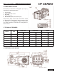
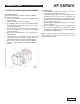
GENERAL PUMP 4. PUMP IDENTIFICATION HF SERIES A member of the Interpump Group Each pump is fitted with a rating plate (see Fig. 1) containing the following information: 2. 3. 4. 5. 6. Serial number Pump model and version Max RPM Power absorbed Max flow rate (l/min) and pressure (bar) Pump model, pump version and serial number should be specified when ordering spare parts. Should the pump be modified (i.
GENERAL PUMP A member of the Interpump Group 7. GENERAL INFORMATION ABOUT PUMP USE HF SERIES 8. CONNECTIONS AND PLUGS The HF pump has been designed to pump fresh filtered (360 micron max) water at room temperature (400 C max). 7.1 Water temperature Water temperature is critical for the pump life, the higher it is, the more likely it is to create cavitation, resulting in premature seal and valve failures. For such conditions, use HT series pumps. 7.
GENERAL PUMP 9. PUMP INSTALLATION A member of the Interpump Group 9.1 Positioning The pump must be installed on a rigid and perfectly flat and horizontal base by means of the proper four M16 x 1.5 threaded feet. The base should be rigid enough to avoid any misalignment or flexing on the pump/transmission coupling axis due to the torque involved during operation. The unit should not be rigidly fixed on the floor but be installed upon vibration dampeners.
GENERAL PUMP A member of the Interpump Group kind of one-way valves. 9. In the case of a feed tank, make sure that dimensions of the tank and the water minimun level do not give rise to turbulence at the tank outlet port, which, in turn might create cavitation in the pump. 10. Do not connect the by-pass line from the valve directly to the pump suction line. 11.
GENERAL PUMP A member of the Interpump Group 9.7 Internal Diameter of Piping To determine the internal diameter of the piping, follow the following diagram. HF SERIES Example 1 ( ) With a flow of 150 l/min and a water speed of 0.45 m/sec, the diagram line joining the 2 scales intersects the central scale, indicating the diameters, at a value of 80 mm. Example 2 ( ) With a flow of 70 l/min and a water speed 5.5 m/sec.
GENERAL PUMP A member of the Interpump Group 10. START UP AND RUNNING PROCEDURES 10.1 Before start up Before start up make sure that the following conditions have been complied with: 1. Suction line should be connected: the pump must never run dry. 2. Suction line must be perfectly air-tight. 3. Any ON-OFF valve in between the pump and water source should be open and make sure the water gets into the pump freely. 4.
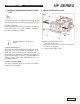
GENERAL PUMP A member of the Interpump Group 11. MAINTENANCE INSTRUCTIONS 11.1 Crank mechanism maintenance. Check oil level at least on a weekly basis (Fig. 8). If necessary, add the missing oil through the oil plug (position 1, Fig. 8). Check oil level when the pump is at room temperature. When changing the oil (removing the plug position 3, Fig. 8), the pump should be at its working temperature. Change oil every 1000 working hours, oil pump capacity is 2 litres.
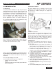
GENERAL PUMP A member of the Interpump Group 11.1.1 Crank mechanism disassembling Do as follows: A) Drain the oil from the pump and remove: - shaft key -back cover -connecting rod cap - side covers. To do so, use 3 screws (M6 x 50) wholly threaded, putting them into the holes drilled for that purpose. See Fig. 9. HF SERIES 11.1.
GENERAL PUMP A member of the Interpump Group C) Before reassembling the side covers, check the seal lips for wear. If they need replacing, fit the new ring following the indications in Fig. 12. HF SERIES E) Fit the back cover putting the dipstick hole upward. 11.1.3 Disassembling / Reassembling of the bearings and shims The type of bearings (conical roller) ensures there is no end float on the crankshaft; the shims are to be determined to reach that purpose.
GENERAL PUMP HF SERIES A member of the Interpump Group 11.1.4 Disassembling / reassembling of the crankshaft with replacement of the bearings After disassembling the side covers, as indicated in point 11.1.1, remove the outer ring nut of the bearings from their covers and the inner ring nut, together with the remaining part of the bearing, from the 2 shaft ends by means of a standard pin extractor or similar tool. See Fig. 15-16. Measure Shim Type # Pieces From: 0.11 to 0.20 0.1 1 From: 0.
GENERAL PUMP A member of the Interpump Group 11.2 Fluid end maintenance 11.2.1 Pump head The pump head does not require periodic maintenance. Service operations are limited to the component inspections and/or replacement, when necessary. HF SERIES A) Loosen the valve cover screws (not shown). B) Extract the valve plugs with an extractor or a M8 threaded rod (see Fig. 19). C) Extract the valve unit with the same tool.
GENERAL PUMP A member of the Interpump Group Valve components of each valve are pressed together and therefore they can be easily replaced and installed back in place by means of simple tools (see Fig. 22). Check the components for wear and replace if necessary. Replace all o-rings of the valve units and valve plugs, at each inspection. 11.2.2 Seals HF SERIES The replacement of the seals is necessary when water drips throught the holes provided underneath the crankcase.
GENERAL PUMP HF SERIES A member of the Interpump Group Take note of the correct order of the entire package components when disassembling (Fig. 26): 1. Head ring 2. HP packing 3. “Restop” ring 4. Middle ring 5. LP packing 6. Back packing 7. Elastic ring 8. O-ring Fit the fluid end back in place and tighten the bolts with a torque wrench set for the value indicated in the table on page 18 and in the sequence indicated here below. When reassembling, make sure of the correct order of the components. 11.
GENERAL PUMP HF SERIES A member of the Interpump Group 11.2.4 Fluid End In order to mount the fluid end on the pump proceed as follows: A) Fit the packing supports back in place in the crankcase. B) Fit the pressure packings back in place in the pump head. C) Using two stud bolts (min. length: 200 mm) and the central plunger as a guide carefully slide to head in position against the crankcase. D) Tighten the head bolts with a torque wrench set as indicated in the chart to the right. 12.
GENERAL PUMP A member of the Interpump Group 14. PUMP STOPPED FOR LONG TIME HF SERIES Before starting the pump for the very first time after a long period from the date of shipment check for the correct oil level, check the valves as indicated in chapter 11 and then comply with the starting procedures indicated in chapter 10.
GENERAL PUMP A member of the Interpump Group 17.
GENERAL PUMP Item Part # 1 F71010022 3 F90391800 2 4 5 6 7 8 9 10 11 12 13 14 15 16 17 18 19 20 21 22 23 24 25 26 27 28 29 30 31 32 33 34 35 36 37 38 38 F91859000 F71220081 F71220381 F71220581 F90075600 F70211801 F90387700 F71150122 F99186700 F90384100 F98218300 F98212000 F71160022 F90400000 F98206000 F99313800 F71020035 F91500000 F71150022 F90170000 F71030043 F90060600 F71050015 F97743000 F90167800 F96714000 F71040009 F71040109 F71040209 F90367100 F71219566 F90079700 F71217070 F71217170 F712174
GENERAL PUMP A member of the Interpump Group 18. TROUBLE SHOOTING THE PUMP DOES NOT PRODUCE ANY NOISE: - The pump is not primed and is running dry! - No water in the inlet line - The valves are blocked - The pressure line is closed and does not allow the air to get out the fluid end. THE PUMP KNOCKS: - Air suction. - Insufficient feeding: - bends, elbows and fittings along the suction line throttle the amount of water which passed through. - too small inlet filter. - dirty inlet filter.
GENERAL PUMP A member of the Interpump Group 19. MAINTENANCE TOOLS The pump maintenance can be carried out with simple tools for mounting and dismounting, but tools can be made to facilitate these operations. The drawings here below will help the operator make tool if he wants to. HF SERIES 19.2 Piston guide oil seal assembling 19.
GENERAL PUMP MAINTENANCE LOG A member of the Interpump Group HF SERIES HOURS & DATE OIL CHANGE GREASE PACKING REPLACEMENT PLUNGER REPLACEMENT VALVE REPLACEMENT GP Companies, Inc. 1174 Northland Drive Mendota Heights, MN 55120 Phone:651.686.2199 Fax: 800.535.1745 www.generalpump.com email: sales@gpcompanies.com Ref 300622 Rev.