
Repair Manual


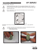

Insert the inlet and outlet valve units with their related bushings checking that they are thouroughly inserted
in their seat on the head. Therefore apply the valve covers and proceed with calibrating the related M14x40
screws; see the indications in Chapter 3, Screw Calibration.
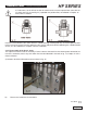
2.2.3 Disassembly of the Head - Seals
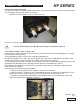
The replacement of the seals is necessary if water leaks are detected from the draining holes located at the
rear of the crankcase, and in any case within the intervals indicated in the table in fig. 14, Chapter 11 of the
Owner’s Manual.
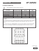
A) Unfasten the M12x150 head screws as shown in fig. 25.
GENERAL PUMP
A member of the Interpump Group
HF SERIES
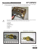
B) Remove the head from the crankcase.
Page 12
Ref 300623 Rev.A
01-12
2
. Furthermore, for the HF18A version be careful not to invert the sperical inlet valve with the
“A” outlet valve (fig. 23 and fig. 24), exploded view position #46, as indicated in Chapter 16
of the Owner’s manual