KEZ Repair Manual
GENERAL PUMP INDEX 1. 2. 3. 4. A member of the Interpump Group KEZ SERIES INTRODUCTION . . . . . . . . . . . . . . . . . . . . . . . . . . . . . . . . . . . . . . . . . . . . . . . . . .Page 3 REPAIR ISTRUCTIONS . . . . . . . . . . . . . . . . . . . . . . . . . . . . . . . . . . . . . . . . . . . . .Page 3 2.1 Crank Mechanism Repair . . . . . . . . . . . . . . . . . . . . . . . . . . . . . . . . . . . . . . . . .Page 2.1.1 Crank mechanism disassembly . . . . . . . . . . . . . . . . . . . . . . . . .
GENERAL PUMP 1. INTRODUCTION A member of the Interpump Group KEZ SERIES This manual describes the instructions for repairing the KEZ Pump, and must be carefully read and understood before performing any repair intervention on the pump. Correct use and adequate maintenance is fundamental for the pumps regular operation and long duration. General Pump declines any responsibility for damage caused by misuse or the non-observance of the instructions described in this manual. 2. REPAIR INSTRUCTIONS 2.
GENERAL PUMP A member of the Interpump Group 2.1.1 Crank mechanism disassembly The correct sequence is the following: A) Dissasemble: • pump shaft key • rear cover • connecting rod cap • side covers, using 3 wholly threaded M6 x 50 screws, inserting them in the holes as shown in fig. 2. KEZ SERIES fig. 2 B) Push the plunger guides and connecting rods forward in order to facilitate the lateral extraction of the crankshaft.
GENERAL PUMP A member of the Interpump Group KEZ SERIES B) Before reassembly of the side covers, check the seal lips for wear. If replacement is necessary, position the new ring using the correct tool (#F27904500) as shown in fig. 5. If the shaft presents diameter wear corresponding to the sealing lip, to avoid the need for griding it’s possible to position the ring as indicated in fig. 5.
GENERAL PUMP A member of the Interpump Group KEZ SERIES D) Install the connecting rod cap respecting numbering, and fasten the relevant bolts (lubricating both the head and the threaded stem) proceeding in three different steps, see fig. 7. 1. Approaching torque 4-6 ft. lbs. (6-8 Nm) 2. Pre-fastening torque 18-20 ft. lbs. (25-28 Nm) 3. Fastening torque 28 ft. lbs. (38 Nm) E) After setting the torque, check that the big end of the connecting rod has a lateral play in both directions.
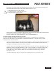
GENERAL PUMP A member of the Interpump Group KEZ SERIES B) Disassembly/assembly of the crankshaft with bearing replacement After disassembling the side covers as indicated in paragraph 2.1.1, remove the outer ring nut of the bearings from their covers and the inner ring nut, with the remaining part of the bearing, from the two shaft extremeties using a standard pin extractor or similar tool as indicated in figures 8 and 9. fig. 8 fig.
GENERAL PUMP A member of the Interpump Group KEZ SERIES fig. 10 Determine the shim pack as indicated in the table below. Measurement Shim Type # Pieces From: 0.11 to: 0.20 0.1 1 From: 0.31 to: 0.35 0.25 1 From: 0.46 to: 0.55 0.35 0.10 From: 0.05 to: 0.10 From: 0.21 to: 0.30 From: 0.36 to: 0.45 From: 0.56 to: 0.60 From: 0.61 to: 0.70 / 0.1 0.35 0.25 0.35 0.25 / 2 1 1 1 2 1 1 E) Insert the shims under the cover on the sight glass side (see fig.
GENERAL PUMP 2.2 Fluid End Repair A member of the Interpump Group KEZ SERIES 2.2.1 Disassembly of the head - valve units Service operations are limited to valve inspection or replacement if needed. To extract the valve units proceed as follows: fig. 12 A) Unfasten the 7 M12 x 35 valve cover screws, and remove the cover (fig. 12). B) Remove the valve plugs with an M6 threaded bolt (fig. 12). C) Remove the valve assemblies with a pliers to grab the valve cages (fig. 12).
GENERAL PUMP KEZ SERIES A member of the Interpump Group Disassemble the valve assemblies with simple tools - a couple of screw drivers (fig. 13) would work more than fine. Components valve assemblies are pressed together with a minimal load, therefore the job results extremely easy to be carried out. Being the valve cages are made of polymer, attention should be taken during service in order to prevent the cage ribs from being damaged. fig. 13 2.2.
GENERAL PUMP A member of the Interpump Group KEZ SERIES To facilitate the insertion of the valve guide into its seat, use a tube that lays on the horizontal shoulders of the guide (fig. 16a and use a hammer acting on the entire circumference. fig. 15 fig. 16 fig. 16a Insert the suction and delivery valve units checking that they are thoroughly inserted in the head seat.
GENERAL PUMP A member of the Interpump Group B) Remove the head from the crankcase. KEZ SERIES C) Extract the high pressure seals from the head, and the low pressure seals from their related support by using standard tools as shown in fig. 18; be careful not to damage the seals. Pay careful attention to the order of sealing pack disassembly as shown in Fig.
GENERAL PUMP A member of the Interpump Group KEZ SERIES 2.2.4 Plunger Unit Disassembly The plunger unit does not require periodical maintenance. Service interventions are limited to visual inspections only. For plunger unit extraction, operate as follows: A) Unfasten the plunger screws as shown in fig. 20. fig. 19 B) Check for wear; replace if necessary. At each disassembly, all plunger unit O-rings MUST be replaced. 2.2.
GENERAL PUMP 13. SCREW CALIBRATION Description Cover fastening screws Plunger fastening screws Connecting rod caps fastening screws Valve cover screws Head fastening screws Service plug A member of the Interpump Group Exploded View Position 9 28 36 35 51 16 KEZ SERIES Stainless Steel 8.8 Fastening Torque (ft. lbs.
GENERAL PUMP A member of the Interpump Group 4. REPAIR TOOLS KEZ SERIES Pump repair may be facilitated by using the proper tools. See Below. For Assembly: Packing Insertion Guide, HP, Dia.
GENERAL PUMP MAINTENANCE LOG A member of the Interpump Group KEZ SERIES HOURS & DATE OIL CHANGE GREASE PACKING REPLACEMENT PLUNGER REPLACEMENT VALVE REPLACEMENT GP Companies, Inc. 1174 Northland Drive Mendota Heights, MN 55120 Phone:651.686.2199 Fax: 800.535.1745 www.generalpump.com email: sales@gpcompanies.com Ref 300666 Rev.