KFM Repair Manual
GENERAL PUMP INDEX 1. 2. 3. 4. A member of the Interpump Group KFM SERIES INTRODUCTION . . . . . . . . . . . . . . . . . . . . . . . . . . . . . . . . . . . . . . . . . . . . . . . . . .Page 3 REPAIR INSTRUCTIONS . . . . . . . . . . . . . . . . . . . . . . . . . . . . . . . . . . . . . . . . . . .Page 3 2.1 Crank Mechanism Repair . . . . . . . . . . . . . . . . . . . . . . . . . . . . . . . . . . . . . . . . .Page 2.1.1 Crank mechanism disassembly . . . . . . . . . . . . . . . . . . . . . . . . . .
GENERAL PUMP KFM SERIES A member of the Interpump Group 1. INTRODUCTION This manual describes the instructions for repairing the KFM Series Pumps, and must be carefully read and understood before performing any repair intervention on the pump. Correct use and adequate maintenance is fundamental for the pump’s regular operation and long duration. General Pump declines any responsibility for damage caused by misuse or the non-observance of the instructions described in this manual. 2.
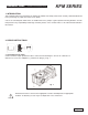
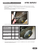
GENERAL PUMP A member of the Interpump Group 2.1.1 Crank mechanism disassembly The correct sequence is the following: A) Dissasemble: • pump shaft key • rear cover • connecting rod cap • side covers, using 3 wholly threaded M6 x 50 screws, inserting them in the holes as shown in fig. 2. KFM SERIES B) Push the plunger guides and connecting rods forward in order to facilitate the lateral extraction of the crankshaft. Two marks are visible on the crankshaft (3), as shown in fig. 3 and fig.
GENERAL PUMP A member of the Interpump Group KFM SERIES 2.1.2 Crank mechanism assembly After cleaning the crankcase, reassemble the crankcase mechanism as follows: A) Thoroughly fit the plunger guide seals into their seat on the crankcase as shown in fig. 5a using the proper tool (p/n F27904900). B) Introduce the pre-assembled plunger guide/connecting rod units into their seat; to facilitate tightening of the connecting rod cap, we advise to position the connecting rod so you can easily read the number.
GENERAL PUMP A member of the Interpump Group KFM SERIES Before assembling the cover (sight glass side), be sure that the shim rings have been inserted. To help the covers fit onto the crankcase, we advise using 3 screws M6 x 40, and then finish the operation with the screws supplied (M6 x 8) as shown in fig. 6. D) Install the connecting rod cap respecting numbering, and fasten the relevant bolts (lubricating both the head and the threaded stem) proceeding in three different steps, see fig. 7. 1.
GENERAL PUMP A member of the Interpump Group KFM SERIES installing the complete unit (sight glass flange + shaft + engine side flange), check that the shaft’s rolling torque - with the connecting rods free - is a least 3 ft. lbs. (4 Nm), max 4 ft. lbs. (6 Nm). To position the two side covers on the crankcase, initially use 3 screws, M6 x 40 as shown in fig. 6, and then fastening the screws. The shaft’s rolling torque (with the connecting rods coupled) must not exceed 6 ft. lbs. (8 Nm).
GENERAL PUMP A member of the Interpump Group The shim pack must be redefined as follows: KFM SERIES A) Insert the crankshaft in the crankcase, being sure that the P.T.O. shank comes out of the correct side. B) Fit the P.T.O. side flange to the crankcase paying great attention to the seal lip as indicated in paragraph 2.1.2, section C. C) Position the flange on the sight glass side as indicated in paragraph 2.1.2. D) Use a thickness gauge (see fig. 10).
GENERAL PUMP KFM SERIES A member of the Interpump Group 2.2 Fluid End Repair 2.2.1 Disassembly of the head - valve units Service operations are limited to valve inspection or replacement if needed. To extract the valve units proceed as follows: A) Unfasten the 7 M12 x 35 valve cover screws, and remove the cover (fig. 12). B) Extract the valve plugs using a slide hammer M10 (fig, 12). C) Extract the valve guides using the same slide hammer extractor used for the valve covers. (pos. 4, fig.
GENERAL PUMP KFM SERIES A member of the Interpump Group 2.2.2 Head assembly - valve units Pay careful attention to state of wear of the various components; replace them when necessary, and in any case within the intervals indicated in the table in fig. 14, Chapter 11 of the Owner’s Manual. At each inspection, replace all valve units and valve plugs, o-rings and enti-extrusion rings. Before repositioning the valve seats and the H.P.
GENERAL PUMP A member of the Interpump Group 2.2.3 Disassembly of the head - seals KFM SERIES Replacing the seals is necessary from the moment high losses of bentonite begin appearing from the opening under the spacer, and in any case at the intervals specified in the table in (fig. 14) Chapter 11 of the Owner’s Manual. A) Unscrew the M12 x 220 head fastening screws as shown in fig. 17 and the M12 nuts as shown in fig. 17a. B) Separate the head from the pump housing.
GENERAL PUMP A member of the Interpump Group KFM SERIES 2.2.4 Plunger Unit Disassembly The plunger unit does not require periodical maintenance. Service interventions are limited to visual inspections only. For plunger unit extraction, operate as follows: A) Pull out the spacer and loosen the M7 x 1 plunger fastening screws as shown in fig. 20. B) Check and verify their state of wear, and replace them if necessary. Check and verify the state of wear of the spacers located behind the plunger (fig.
GENERAL PUMP 13. SCREW CALIBRATION Description Cover fastening screws Plunger fastening screws Connecting rod caps fastening screws Head fastening nut Head fastening screws Valve cover screws Lifting bracket fastening screws Oil Discharge plug Delivery duct plug A member of the Interpump Group Exploded View Position 9 54 45 48 29 17 11 42 18 KEZ SERIES 8.8 AISI 416 Fastening Torque (ft. lbs.) 7 15 Fastening Torque (Nm) 10 20 8.8 8.8 12.9 8.
GENERAL PUMP A member of the Interpump Group 4. REPAIR TOOLS KFM SERIES Pump repair may be facilitated by using the proper tools. See Below.
GENERAL PUMP A member of the Interpump Group 4.
GENERAL PUMP MAINTENANCE LOG A member of the Interpump Group KFM SERIES HOURS & DATE OIL CHANGE GREASE PACKING REPLACEMENT PLUNGER REPLACEMENT VALVE REPLACEMENT GP Companies, Inc. 1174 Northland Drive Mendota Heights, MN 55120 Phone:651.686.2199 Fax: 800.535.1745 www.generalpump.com email: sales@gpcompanies.com Ref 300693 Rev.