
Repair Manual Manual


GENERAL PUMP
A member of the Interpump Group
KFM SERIES
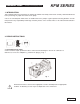
2.1.1 Crank mechanism disassembly
The correct sequence is the following:
A) Dissasemble:
• pump shaft key
• rear cover
• connecting rod cap
• side covers, using 3 wholly threaded M6 x 50 screws, inserting
them in the holes as shown in fig. 2.
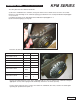
B) Push the plunger guides and connecting rods forward in order to facilitate the lateral extraction of the
crankshaft. Two marks are visible on the crankshaft (3), as shown in fig. 3 and fig. 3a; they must be turned
towards the operator in order to facilitate extraction.
NOTE: to extract the plunger guide it is necessary to remove the ceramic plunger, spacer and wiper first.
C) Disassemble the crankshaft oil seals and the plunger guides using standard tools.
Page 4
fig. 3a
fig. 3a