
Repair Manual Manual


GENERAL PUMP
A member of the Interpump Group
KFM SERIES
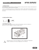
installing the complete unit (sight glass flange + shaft + engine side flange), check that the shaft’s rolling
torque - with the connecting rods free - is a least 3 ft. lbs. (4 Nm), max 4 ft. lbs. (6 Nm). To position
the two side covers on the crankcase, initially use 3 screws, M6 x 40 as shown in fig. 6, and then fastening the
screws. The shaft’s rolling torque (with the connecting rods coupled) must not exceed 6 ft. lbs. (8 Nm).
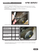
B) Disassembly/assembly of the crankshaft with bearing replacement
After disassembling the side covers as indicated in paragraph 2.1.1, remove the outer ring nut of the
bearings from their covers and the inner ring nut, with the remaining part of the bearing, from the two shaft
extremeties using a standard pin extractor or similar tool as indicated in figures 8 and 9.
The new roller bearing can be mounted at room temperature with a press or fly press; it is necessary to lay
them on the lateral side of the relevant ring nuts with correct rings. The driving operation can be facilitated
by heating the relevant parts at a temperature ranging between 250
0
-300
0
F (120
0
-150
0
C), making sure
that the ring nuts are correctly fitted into their seats.
Never invert the parts of the two bearings.
Page 7