
Owner Manual Owner manual


GENERAL PUMP
A member of the Interpump Group
KS SERIES
6. Do not install Venturi tubes or injectors for detergent
intake.
7. Avoid the use of standing valves, check valves, or any
other type of one-way valves.
8. Do not connect the by-pass line from the valve directly
to the pump suction line.
9. Provide appropriate baffle plates inside the tank in
order to avoid that water flows coming from both the by-
pass and feeding lines may create turbulence near the
tanks outlet port.
10. Make sure that the suction line is perfectly clean inside
before connecting it to the pump.
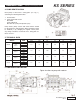
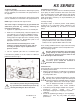
9.7 Filtering
On the pump suction line, install 2 filters arranged as shown
in fig 7 and fig. 7a.
The filter must be installed as close as possible to the
pump, should allow easy inspection and have the follow-
ing characteristics:
1. Minimum capacity 3 times greater than the pump’s
rated flow value.
2. Filter port diameters must not be smaller than the
pump inlet ports.
3. Filtration degree ranging between 200 and 360 µm.
In order to guarantee correct pump opera-
tion, it is important to plan periodical
cleaning of the filter depending on actual
pump usage, water quality and real
clogging conditions.
9.8 Delivery line
For a correct delivery line comply with the following
instructions:
1. The internal diameter of the pump must allow to
guarantee correct fluid speed; see diagram in
paragraph 9.9.
2. The first length of delivery hose should be flexible
in order to isolate the pump vibrations from the
rest of the system.
3. Use only high pressure hoses and fittings able to
guarantee the largest possible safety margins in
any working conditions.
4. A suitable relief valve should be installed in the
delivery line.
5. Use pressure switches suitable for the pulsating loads
typical of plunger pumps.
6. When designing the delivery line, take into proper
account the unavoidable drop in pressure, due to
its length and size.
7. If necessary, the effects of the pump pulsations
can be reduced by installing a proper pulsation
dampener in the pressure line.
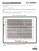
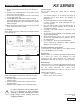
9.9 Internal Diameter of the Piping
To determine the internal diameter of the piping, please
refer to the diagram on the next page.
Suction Pipe
With a flow rate of ~ 226 l/min (60 GPM) and water speed
of 1 m/sec (3.3 ft/sec). The diagram line that
connects the two scales intersects the central scale,
indicating the diameters, at a value of ~ 70 mm (2.76 in.).
Delivery Pipe
With a flow rate of ~ 226 l/min (60 GPM) and water speed
of 5.5 m/sec (18 ft./sec). The diagram line that connects
the two scales intersects the central scale,
indicating the diameters, at a value of ~ 30 mm (1.2 in.).
Optimum Speed Values
• Suction: ≤ 1 m/sec (3.3 ft./sec)
• Delivery: ≤ 5.5 m/sec (18 ft./sec)
Page 10
Ref 300655 Rev D
09-12