
Owner Manual Owner manual


GENERAL PUMP
A member of the Interpump Group
KS SERIES
Page 8
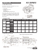
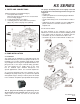
8. PORTS AND CONNECTIONS
KS Series pumps are provided with (fig 4):
1 - 2 inlet ports IN Ø 2” NPT-F
Either inlet port can be used; the one not used must
be hermetically plugged.
2 - 2 outlet ports OUT Ø 1-1/2” NPT-F
3 - 3 auxiliary ports, 3/4” Gas; used for the pressure
gauge only, and for verifying correct priming.
9. PUMP INSTALLATION
9.1 Installation
The pump must be installed on a rigid and perfectly flat
and horizontal base by means of the proper four M16 x 1.5
threaded feet. The base should be rigid enough to avoid
any misalignment or flexing on the pump/transmission cou-
pling axis due to the torque involved during operation.
The unit should not be rigidly fixed on the floor
but be installed upon vibration dampeners. For
special applications contact our technical department.
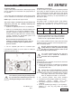
An eye-bolt is provided on top of the crankcase for easy
handling of the pump. below). The eye bolt can be replaced
with a plastic cap (see below), in order to protect the thread
in the crankcase.The plastic cap is provided with the pump.
The pumps shaft (PTO) must not be rigidly connected
to the motor unit. The following transmission types are
suggested:
• Flexible joint
• Cardan joint (within the max working angles indicated
by the manufacturer).
• V-belts; allowed only for the versions without a reducer
unit.
• Hydraulic by means of a flange; for correct application,
please contact the Technical or Customer Service
Departments.
The oil plug must absolutely be replaced by the oil
stick and the oil level checked. Make sure that you can
easily reach the oil stick even after the unit has been
assembled.
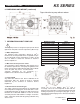
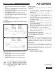
9.2 Direction of rotation
An arrow situated on the crankcase near the shaft
indicates the correct direction of rotation. Standing in front
of the pump head, the direction of rotations must be:
• as shown in fig. 5 for versions with a reducer unit
• as shown in fig. 5a for versions without a reducer unit
Ref 300655 Rev D
09-12