
Owner Manual Owner manual


GENERAL PUMP
A member of the Interpump Group
KS SERIES
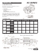
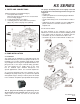
9.3 Version Change
A right version pump is defined when: Observing the pump
from the head side, the PTO shank of the pump shaft is on
the right side.
A left version pump is defined when observing the pump
from the head side, the PTO shank of the pump shaft is on
NOTE: Figures 5 and 5a show right versions.
The version may be changed only by specialized and
authorized personnel by carefully following the
instructions that follow:
1. Separate the hydraulic part from the mechanical part.
2. Rotate the mechanical part by 180
0
, and reposition the
rear crankcase cover so that the oil dipstick is facing
upwards; reposition the lifting bracket and the related
closing caps in the upper part of the crankcase; finally,
correctly reposition the identification plate in its
appropriate seat on the crankcase.
Be sure that the lower draining holes on the
crankcase near the plungers are open, and not
closed by the plastic caps as required for the
previous version.
3. Join the hydraulic part with the mechanical part.
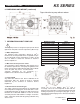
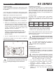
It is furthermore possible to set the reducer in 4 different
positions as shown in fig. 6.
9.4 Hydraulic Connections
In order to isolate the system from the vibrations produced
by the pump, we advise to build the first section of the duct
near the pump (both for intake and delivery) with flexible
tubes. The consistency of the intake section must allow to
avoid deformation caused by the depressurization pro-
duced by the pump.
9.5 Pump Feeding
KS pumps require a minimum positive head (NPSH
r
),
measured on the head intake flange, indicated in the
following table (obtainable by the means of a booster
pump):
The reducer’s position may be changed only
by specialized and authorized personnel by
carefully following the above directions.
KS28A KS32A KS36A KS40A
NPSH
r
(m)
2.0 2.5 3.0 4.0
The booster pump must have the following characteristics:
• Flow rate of at least twice the value of the plunger
pump’s rated flow value, with a minimum pressure
sufficient for the required NPSH
r
and max 87 PSI.
These feeding conditions must be respected in all running
conditions. Booster activation must be independent from
that of the plunger pump.
Booster start-up must always precede plunger
pump start-up. In order to protect the pump,
we advise to install a pressure switch on the
feeding line after the filters.
For feeding conditions that differ from that speci-
fied above, please contact the Technical or
Customer Service Department.
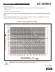
9.4 Suction line
For the pumps correct operation, the suction line must have
the following characteristics:
1. Minimum internal diameter as indicated in the diagram
in paragraph 9.9, and in any case equal or greater than
the pump head’s value.
Along the duct, avoid localized diameter reduction
that may cause pressure drops with subsequent
cavitation. Absolutely avoid 900 elbows, with other
tubes, pipes, bottlenecks, counter-slopes, upside-
down “U” shaped curved and “T” connections.
2. The selection position must avoid cavitation.
3. It should be perfectly airtight, and built in a way that
guarantees perfect sealing over time.
4. Avoid pump emptying when stopping (even partial
emptying).
5. Do not use hydraulic-type fittings, 3- or 4-way fittings,
adapters, etc., since they may hinder the pump’s
performance.
Page 9
Ref 300655 Rev D
09-12