LH Owner’s Manual • Installation • Use • Maintenance
GENERAL PUMP INDEX A member of the Interpump Group LH SERIES 1. INTRODUCTION . . . . . . . . . . . . . . . . . . . . . . . . . . . . . . . . . . . . . . . . . . . . . . . . . .Page 3 3. SAFETY . . . . . . . . . . . . . . . . . . . . . . . . . . . . . . . . . . . . . . . . . . . . . . . . . . . . . . . . .Page 3.1 General warnings for safe operation . . . . . . . . . . . . . . . . . . . . . . . . . . . . . . . .Page 3.2 High pressure unit safety requirements . . . . . . . . . . . . . . . . . . . . . .
GENERAL PUMP 1. INTRODUCTION A member of the Interpump Group LH high pressure water plunger pumps have been designed for long life industrial duties and provided they are correctly installed and maintained will give long trouble-free operation. Read and understand this manual before using your pump; it contains the necessary information for the correct installation, use and maintenance as well as some practical suggestion for trouble shooting.
GENERAL PUMP A member of the Interpump Group 3.3 Safety of operation The access into the area when a high pressure unit is working should be strictly prohibited to unauthorized personnel. The area should be suitably enclosed and its perimeter, so far as is reasonably practical, cordoned off and proper warning notices displayed in prominent positions.
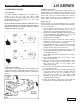
GENERAL PUMP 4. PUMP IDENTIFICATION LH SERIES A member of the Interpump Group Each pump is fitted with a rating plate (see Fig. 1) containing the following information: 2. 3. 4. 5. 6. 7. 8. pump model and version serial number max RPM max operating pressure (bar) oil capacity (ltr) and oil specification gear box ratio max flow rate (l/min) Pump model, pump version and serial number should be specified when ordering spare parts. Should the pump be modified (i.
GENERAL PUMP A member of the Interpump Group 7. GENERAL INFORMATION ABOUT PUMP USE LH SERIES 8. CONNECTIONS AND PLUGS The LH pump has been designed to pump fresh filtered water at room temperature. LHZ and LHN special stainless steel versions are also available for critical fluids. 7.1 Water temperature Water temperature is critical for the pump life, the higher it is, the more likely it is to create cavitation, resulting in premature seal and valve failures.
GENERAL PUMP 9. PUMP INSTALLATION A member of the Interpump Group 9.1 Positioning The pump should be installed flat on a rigid base by means of the four 3/4” feet. The base should be rigid enough to avoid any misalignment or flexing of the pump/transmission coupling axis due to the torque involved during operation. On no account should the pump be installed in such a way its fluid end rests on the base where the pump is mounted. The fluid end should be left free and not subjected to any force. (Fig 4).
GENERAL PUMP A member of the Interpump Group LH SERIES 9.5 Filtration All pumps require a suitable filter. The filter should be installed as close as possible to the pump, should allow easy inspection and have the following characteristics: 1. The filter capacity should be at least three times the rated pump volume. 2. Filter port diameters should not be smaller than the pump inlet ports. 3. Filtration degree in between 50 and 80 mesh (360 to 200 microns.
GENERAL PUMP A member of the Interpump Group 10. START UP AND RUNNING PROCEDURES 10.1 Before start up Before start up make sure that the following conditions have been complied with: 1. Suction line should be connected: the pump must never run dry. 2. Suction line must be perfectly air-tight. 3. Any ON-OFF valve in between the pump and water source should be open and make sure the water gets into the pump freely. 4.
GENERAL PUMP A member of the Interpump Group 11. MAINTENANCE INSTRUCTIONS 11.1 Crank mechanism maintenance. Check oil level through the oil level indicator 1, Fig 8 at least on a weekly basis. LH SERIES 11.2 Fluid end maintenance The fluid end does not require periodical maintenance. Service operations are limited to valve inspection and/or replacement, when necessary. In order to remove the valves: Loosen and remove the valve cover screws (1, Fig. 9). If necessary, top up from the oil plug 3, Fig. 8.
GENERAL PUMP A member of the Interpump Group LH SERIES Should excessive scaling inside the fluid end hinder the valve extraction open one of the two lateral inlet ports, remove the three plugs, Fig. 15, insert our special tool p/n F200030090 (or a corresponding one) and push the valve unit out as shown in Fig. 15. Check the valve components for wear and replace where necessary. Every time valves are inspected, all o-rings and valve covers should be replaced.
GENERAL PUMP A member of the Interpump Group 11.3 Pumping unit maintenance The only maintenance operation required for the pumping unit is to periodically check the amount of water drained out by the pump through the hole provided in the lower cover (Fig 6, page 9). It clearly shows the pressure packing state of wear; replace them if water dripping becomes continuous and not intermittent. LH SERIES For inspecting the pumping unit, remove the head by loosening the eight head screws (1, Fig. 16).
GENERAL PUMP A member of the Interpump Group Disassemble the packing support from the cylinder by means of a pin key (1, Fig. 20). LH SERIES In order to fit the new scraper in place, shape it manually as shown in Fig. 22. VERY IMPORTANT! The scraper is provided with an internal lip which performs the correct scraping effect only if oriented toward the fluid end. See window inside Fig. 22.
GENERAL PUMP A member of the Interpump Group Set up the complete package without tightening the packing support (1, Fig. 24) but making sure that the pressure packings snap in place. LH SERIES Fit the pumping units back in the pump crankcase (1, Fig. 26). Tighten the plunger screws with a torque wrench set for 72 ft. lbs. Mount the head back in place and tighten the eight head screws with a torque wrench set for 260 ft. lbs.
GENERAL PUMP A member of the Interpump Group 12. SCREW CALIBRATION Screw calibration is to be carried out by means of a torque wrench only: DESCRIPTION Ft. Lbs. Head Bolts 260.3 Connecting Rod Screws 54.2 Valve cover screws Plunger bolts N-m Kgm. 353 36 86.7 117.6 72.3 98 13. MAINTENANCE TOOLS 73.5 12 10 7.
GENERAL PUMP A member of the Interpump Group 16.
GENERAL PUMP Item 1 2 3 4 5 6 7 8 9 10 11 12 13 14 15 16 17 18 19 20 21 22 23 24 25 26 27 28 29 30 31 32 33 34 35 36 37 38 39 40 41 42 43 44 45 46 47 48 49 50 51 52 53 54 55 Part # Description F010100070 Left fearing support F881010133 F030000010 F881010132 F871121152 F063400280 F871131102 F030000020 F811111017 F871125154 F871115152 F040400050 F080600030 F872043008 F821203006 F801053012 F872043002 F801057002 F063400240 F080600010 F060100160 F881010116 F801054027 F872026003 F030000030 F0806000
GENERAL PUMP A member of the Interpump Group LH SERIES Page 18
GENERAL PUMP Item Part # 1 F881010133 3 F030000010 2 4 5 6 7 8 9 10 11 12 13 14 15 16 17 18 19 20 21 22 23 24 25 26 27 28 29 30 31 32 33 34 35 36 37 38 39 40 41 42 43 44 45 46 47 48 49 50 51 52 53 54 55 56 57 58 F010100070 F881010132 F871121152 F063400280 F871131102 F030000020 F811111017 F871125154 F871115152 F040400050 F080600030 F872043008 F821203006 F801053012 F872043002 F801057002 F063400240 F080600010 F060100160 F881010116 F801054027 F872026003 F030000030 F080600020 F040400030 F801056002
GENERAL PUMP A member of the Interpump Group 17. TROUBLE SHOOTING LH SERIES THE PUMP DOES NOT PRODUCE ANY NOISE: the pump is not primed and is running dry! - No water in the inlet line - The valves are blocked - The pressure line is closed and does not allow the air to get out the fluid end. INSUFFICIENT PUMP PRESSURE: - The nozzle is (or has become) too large.
GENERAL PUMP MAINTENANCE LOG A member of the Interpump Group LH SERIES HOURS & DATE OIL CHANGE GREASE PACKING REPLACEMENT PLUNGER REPLACEMENT VALVE REPLACEMENT GP Companies, Inc. 1174 Northland Drive Mendota Heights, MN 55120 Phone:651.686.2199 Fax: 800.535.1745 www.generalpump.com email: sales@gpcompanies.com Ref 300018 Rev.