MKS Repair Manual MKS40A-MKS45A-MKS50A MKS55A-MKS60A-MKS65A General Pump is a member of the Interpump Group 8 Ref 300699 Rev B 05-13
GENERAL PUMP INDEX 1. 2. 3. 4. 5. A member of the Interpump Group MKS SERIES INTRODUCTION . . . . . . . . . . . . . . . . . . . . . . . . . . . . . . . . . . . . . . . . . . . . . . . . . .Page 3 REPAIR INSTRUCTIONS . . . . . . . . . . . . . . . . . . . . . . . . . . . . . . . . . . . . . . . . . . .Page 2.1 Crank Mechanism Repair . . . . . . . . . . . . . . . . . . . . . . . . . . . . . . . . . . . . . . . . .Page 2.1.1 Crank Mechanism Disassembly . . . . . . . . . . . . . . . . . . . . . . . . .
GENERAL PUMP A member of the Interpump Group 1. INTRODUCTION MKS SERIES This manual describes the instructions for Repairing MKS Series pumps, and must be carefully read and understood before performing any repair intervention on the pump. Correct use and adequate maintenance is fundamental for the pump’s regular operation and long wear. General Pump declines any responsibility for damage caused by the misuse or the non-observance of the instructions described in this manual. 2. REPAIR INSTRUCTIONS 2.
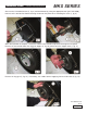
GENERAL PUMP A member of the Interpump Group 2.1.1 Crank Mechanism Disassembly The correct sequence is the following MKS SERIES Completely drain the oil from the pump, then remove the key from the shaft (1, fig.2). Unscrew the reducer flange fastening screws (1, fig. 3) and remove the flange from the shaft. On the opposite side, unfasten the screws (1, fig. 4) and then remove the bearing cover.
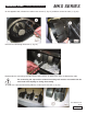
GENERAL PUMP A member of the Interpump Group MKS SERIES Disassemble the crankcase cover by unfastening the relevant screws (1, fig. 5). Unfasten the reducer cover screws (1, fig. 6). Insert 3 dowels, or 3 M8 threaded screws (1, fig. 7) in the appropriate holes to aid extraction, and two sufficiently long M10 screws in order to support the cover (2, fig. 7).
GENERAL PUMP A member of the Interpump Group MKS SERIES Screw on the 3 threaded screws (1, fig. 8) and simultaneously, using the appropriate tool (p/n F27516700), hammer on the tool itself so that the bearing remains on the pinion when extracting the cover (1, fig. 9). When this operation is complete, remove the reducer cover and then slip off the bearing from the pinion. Remove the screws that fasten the ring gear stopper (1, fig. 10), and remove the stopper itself (1, fig. 11).
GENERAL PUMP A member of the Interpump Group MKS SERIES Remove the key from the shaft (1, fig. 13). Remove the pinion by using a slide hammer applying it to the M14 hole (1, fig. 14). Lift the safety washer key (1, fig.
GENERAL PUMP A member of the Interpump Group MKS SERIES Insert a spacer under the connecting rod to block shaft rotation (1, fig. 16). Using an appropriate wrench, unscrew and remove the ring nut (1, fig. 17) and then remove the safety washer (1, fig 18). Screw a SKF KM19 type ring nut onto the pressure sleeve (1, fig. 19), then loosen the sleeve using an appropriate wrench (1, fig. 20).
GENERAL PUMP A member of the Interpump Group MKS SERIES On the opposite side, unfasten the reducer case screws (1, fig. 21), and then remove the case (1, fig. 22). Unscrew the connecting rod screws (1, fig. 23). Disassemble the connecting rod caps with the split bearings; be particularly aware of disassembly order. The connecting rod caps and the related connecting rods must be reassembled in the exact order and coupling as during disassembly.
GENERAL PUMP A member of the Interpump Group MKS SERIES Push the connecting rods forward in the direction of the hydraulic side in order to push out the crankshaft. Use the appropriate tool (p/n F27566200) to facilitate this operation (1, fig. 25) Remove the pressure sleeve (1, fig. 26). Remove the upper split bearing of the connecting rods (1, fig. 27).
GENERAL PUMP A member of the Interpump Group MKS SERIES Remove the crankshaft with the help of a hammer on the PTO side (1, fig. 28). Remove the shaft and the bearing (1, fig. 29). On the opposite side, extract the bearing (1, fig. 30) If the replacement of one or more connecting rods or plunger guides is necessary, please operate as follows: Unfasten the screws of the tool (p/n F27566200 to unlock the connecting rods (1, fig.
GENERAL PUMP A member of the Interpump Group MKS SERIES Couple the connecting rods with the previously disassembled caps; be sure to respect numbering (1, fig. 33). Remove the two seeger rings that block the plunger pin by using the appropriate tool (1, fig. 34). Remove the pin (1, fig. 35) and then remove the connecting rod (1, fig. 36).
GENERAL PUMP A member of the Interpump Group MKS SERIES To separate the rod from the plunger guide, unfasten the M10 hexagonal-head screws using a size 17 socket wrench (1, fig. 37). 2.1.2 Crank Mechanism Assembly Proceed with assembly by inverting the precedure indicated in paragraph 2.1.1. The correct sequence is the following: Connect the rod to the plunger guide Insert the Ø5 pin in the appropriate hole on the plunger guide (1, fig.
GENERAL PUMP A member of the Interpump Group MKS SERIES Block the rod using a clamp, and proceed with calibration using a torque wrench (1, fig. 40) as indicated in paragraph 3. “SCREW CALIBRATION” Insert the connecting rod in the plunger guide (1, fig. 36) and then insert the pin (1, fig. 35). Apply the two seeger rings using the correct tool (1, fig. 34). Make sure that conrods, plunger guides and wrist pins can move freely after being assembled together.
GENERAL PUMP A member of the Interpump Group MKS SERIES Insert the shaft (1, fig. 29) until the pre-assembled bearing is aligned with the edge of the crankcase (1, fig. 43). Manually insert the pressure sleeve to maintain the shaft alignment (1, fig. 44). Assemble the reducer case (1, fig. 45) and the related gasket (2, fig 45) using the 6 M12 x 40 screws (1, fig. 46), the 2 M12 x 50 screws (1, fig. 47) and the Ø 12 Grower washers (2, fig. 46 and fig. 47).
GENERAL PUMP A member of the Interpump Group MKS SERIES Completely insert the pressure sleeve on the shaft from the opposite side of the PTO (1, fig. 49 and fig. 50). Pressure sleeve insertion must be done without oil or lubricants. Insert the sleeve until the external surface (tapered) couples perfectly with the inside of the bearing. During insertion, be sure that the bearing remains in contact with the shaft shoulder. Measure the dimension “X” indicated in fig. 51.
GENERAL PUMP A member of the Interpump Group Measure the dimension “X” indicated in fig. 51. MKS SERIES Screw the ring nut and fasten the sleeve until the dimension “X” is reduced by a value ranging between 0.7 and 0.8 mm (fig. 52). Unscrew the ring nut, insert the safety washer (1, fig. 53) and completely screw the ring nut (1, fig. 54); then fold the washer’s locking key (1, fig. 55).
GENERAL PUMP A member of the Interpump Group MKS SERIES Remove the device that blocks the connecting rods using p/n F27566200 (1, fig. 31). Insert the upper split bearings between the connecting rods and the shaft (1, fig. 56). In order to correctly assemble the split bearings, be sure that the split bearings’ reference key in the appropriate seat on the connecting rod (1, fig. 57). Apply the lower split bearings to the caps, (1, fig.
GENERAL PUMP A member of the Interpump Group MKS SERIES Once tightened on the crankshaft, make sure that conrods still have axial right-left endplay. Preassemble the bearing on the pinion (1, fig. 60) and fully insert the pinion in the seat on the reducer case (1, fig. 61) by using a hammer. Apply the 22 x 14 x 100 key in the seat on the shaft (1, fig. 62) and insert the ring gear on the shaft. Fasten the ring gear stopper (1, fig. 63) using the 2 M10 x 25 screws (2, fig. 63).
GENERAL PUMP A member of the Interpump Group MKS SERIES Apply the 3 Ø 12 x 40 pins to the reducer case (1, fig. 64) and insert the gasket (1, fig. 65). Assemble the bearing on the reducer cover (1, fig. 66). Assemble the reducer cover (1, fig. 67) and fasten it using 8 M10 x 50 screws (1, fig. 68). Use a stopper to avoid the bearing coming out of the seat (1, fig. 69). Calibrate the screws with the torque wrench as indicated in paragraph 3.
GENERAL PUMP A member of the Interpump Group MKS SERIES Insert the oil seal inside the reducer flange using the proper tools, p/n F27515900 and F27548200 (1, fig. 70). Before proceeding with oil seal assembly, verify the conditions of the sealing lip. If replacement is necessary, position the new ring as indicated in fig. 71. If the shaft presents diameter wear corresponding to the sealing lip, to avoid the need for grinding it’s possible to position the ring as indicated in fig. 71.
GENERAL PUMP A member of the Interpump Group MKS SERIES Insert the key 16 x 10 x 90 in the pinion. Insert the O-ring in the rear cover (1. fig. 74) and fasten it to the crankcase using 10 M8 x 18 screws (1, fig. 75). Calibrate the screws with the torque wrench as indicated in paragraph 3. “SCREW CALIBRATION” Assemble the bearing cover (and related gasket) (1, fig. 76) using 8 M12 x 30 screws (1, fig. 77). Calibrate the screws with the torque wrench as indicated in paragraph 3.
GENERAL PUMP MKS SERIES A member of the Interpump Group Complete the assembly of the crank mechanism by applying the plugs and lifting eyebolts with the related sealing O-ring. Fill the crankcase with oil as indicated in the use and maintenance manual, paragraph 7.4. 2.1.3 Refurbishing the crank mechanism TABLE UNDERSIZED DIAMETERS FOR CRANKSHAFT AND CONROD BUSHINGS Lower half bushing p/n 0.25 Upper half bushing p/n F90931100 F90930100 0.50 F90931200 F90930200 Max.
GENERAL PUMP A member of the Interpump Group 2.2 Fluid End Repair MKS SERIES 2.2.1 Head Disassembly - Valve Units The head requires preventive maintenance as indicated in the use and maintenance manual. Interventions may be limited to valve inspection, or replacement as needed. To extract the valve units operate as follows: Unfasten the 8 M16 x 55 screws of the valve cover (1, fig. 78) and remove the cover (1, fig. 79).
GENERAL PUMP A member of the Interpump Group MKS SERIES Extract the delivery valve unit using a slide hammer applied to the M10 hole of the valve guide (1, fig. 82) If the extraction of the delivery valve unit is particularly difficult (for ex. due to incrustations caused by prolonged pump inactivity) use the extraction tool, p/n F27516400 (for MKS40A, MKS45A or MKS50A, or p/n F27516500 (for MKS55A, MKS60A and MKS65A). Unfasten the valve guide spacer using an 8 mm allen wrench (1, fig. 83).
GENERAL PUMP A member of the Interpump Group MKS SERIES If the extraction of the of the suction valve unit is particularly difficult (for ex. due to incrustations caused by prolonged pump inactivity) use the extraction tool p/n F27516200 (for MKS40A, MKS45A, MKS50A) or p/n F27516300 (for MKS55A, MKS60A and MKS65A) (1, fig. 85) and act as indicated. Unscrew the valve opening device using a 30 mm wrench (1, fig. 86).
GENERAL PUMP A member of the Interpump Group 2.2.2 Head Assembly - Valve Units MKS SERIES Pay careful attention to state of wear of the various components; replace them if necessary. At each valve inspection, replace all valve units and valve plug O-rings. Before repositioning the valve units, clean and perfectly dry the relevant seats in the head indicated by the arrows (1, fig. 88). Proceed with reassembly by inverting the procedure indicated in paragraph 2.2.1.
GENERAL PUMP A member of the Interpump Group MKS SERIES Proceed with the insertion of the valve units (suction and delivery) into the head, paying attention to the correct insertion sequence of the O-rings and anti-extrusion rings. The correct assembly sequence of the valve units in the head is the following: Insert the anti-extrusion ring, exploded view item 4 from Owner’s Manual (1, fig. 92). Insert the O-ring, exploded view item 5 from Owner’s Manual (1, fig. 93).
GENERAL PUMP A member of the Interpump Group MKS SERIES Be sure that the O-ring and the anti-extrusion ring are perfectly fit into their seats. Insert the suction valve unit together with the spacer (1, fig. 94). The valve unit must be fully inserted, as shown in 1, fig. 95. Mount the O-ring, exploded view item 5 from Owner’s Manual (1, fig. 96) and the anti-extrusion ring, exploded view item 15 from Owner’s Manual (2, fig. 96) on the delivery valve seat. Insert the delivery valve unit (1, fig. 97).
GENERAL PUMP A member of the Interpump Group MKS SERIES Insert the anti-extrusion ring, exploded view item 16 in Owner’s Manual (1, fig. 99). Insert the O-ring, exploded view item 17 in Owner’s Manual, (1, fig. 100). Pay particular attention when inserting the O-ring indicated in 1, fig. 101. We advise to use the correct tool p/n F27516000 (for MKS40A, MKS45A and MKS50A) or p/n F27516100 (for MK55SA, MKS60A and MKS65A) in order to avoid cutting the O-ring during insertion.
GENERAL PUMP A member of the Interpump Group Insert the valve seat ring (1, fig 102) and the spring (1, fig. 103). MKS SERIES Assemble the O-ring, exploded view item 17 in Owner’s Manual, (1, fig. 104) and the anti-extrusion ring, exploded view item 21 in Owner’s Manual (2, fig. 104) on the delivery valve plug. Insert the valve plug complete with O-rings and anti-extrusion ring. After assembling the valve unit and the valve plug, apply the valve cover (1, fig.
GENERAL PUMP A member of the Interpump Group MKS SERIES Assemble the head on the pump casing (1, fig. 107) being careful not to bump against the plungers, and fasten the 8 M16 x 180 screws (1, fig. 108). Proceed with calibrating the M16 x 180 screws with the torque wrench as indicated in paragraph 3. “SCREW CALIBRATION” Fasten the 8 M16 x 180 screws starting from the 4 internal screws cross-wise (see fig. 107), and then proceed with the 4 external screws, again fastening cross-wise.
GENERAL PUMP A member of the Interpump Group MKS SERIES 2.2.3 Disassembling the Plunger Unit - Supports - Seals The plunger unit requires a periodical inspection as indicated in the preventive maintenance table of the Owner’s Manual. Interventions only require visual inspections of the draining from the hole in the lower cover. In case of anomolies/oscillations on the delivery pressure gauge, or leaking from the drain hole, proceed with seal inspection and replacement if necessary.
GENERAL PUMP A member of the Interpump Group MKS SERIES Manually rotate the shaft so that the 3 plungers are in the top dead center position. Insert the stopper tool p/n F27516600 between the plunger guide and the plunger (1, fig 113). Turning the shaft, move the plunger forward so that the stopper, moving forward itself, can push out the packing support and the entire plunger unit (1, fig. 114). Extract the packing support and the stopper tool.
GENERAL PUMP A member of the Interpump Group Remove the wiper rings from the plunger guides (1, fig. 116). MKS SERIES If replacement of the plunger guide oil seal is needed, disassemble the oil seal cover by operating as follows: Unfasten the two screws of the oil seal cover (1, fig. 117). Extract the oil seal cover by screwing a threaded M5 bar or screw into the correct holes on the cover (1 fig. 118); extract the oil seal cover from the pump unit (1, fig. 119).
GENERAL PUMP A member of the Interpump Group MKS SERIES Replace the oil seal (1, fig. 120) and the external O-ring (2, fig. 120). Separate the packing support from the liner (1, fig. 121) to access the pressure packings (1, fig 122). To remove the low pressure packing, use a shim or another tool that doesn’t damage the seat of the packing support (1, fig. 123).
GENERAL PUMP A member of the Interpump Group MKS SERIES 2.2.4 Assembly of the Plunger Unit - Support - Seals Proceed with reassembly by inverting the disassembly procedure indicated in paragraph 2.2.3. Replace the pressure packings by applying a small amount of silicone grease to the lips, being careful not to damage them when inserting the liner. At each disassembly, the pressure packings must always be replaced together with all the O-rings.
GENERAL PUMP A member of the Interpump Group MKS SERIES Insert the oil seal in its cover (1, fig. 129) using a stopper p/n F27910900. Position the O-ring (1, fig. 130) in its seat on the oil seal cover, and insert the assembled unit inside the crankcase in the correct space (1, fig. 131). Perfectly insert the cover into its seat (1, fig. 132) being careful not to damage the oil seal lip. Fasten the oil seal cover with 2 M6 x 14 screws (1, fig. 133).
GENERAL PUMP A member of the Interpump Group MKS SERIES Position the wiper complete with its O-ring in its seat on the plunger guide (1, fig. 134 and fig. 135). Insert the 14 x 2 O-ring in its correct seat on the plunger bolt (1, fig. 136). Assemble the plungers on their respective guides (1, fig. 137) and fasten them as in 1, fig. 138). Calibrate the screws using the torque wrench as indicated in paragraph 3.
GENERAL PUMP A member of the Interpump Group MKS SERIES Insert the O-ring inside the pump case (1, fig. 139), followed by the previously assembled liner-packing support unit (complete with the O-ring), (1, fig. 140). Be sure that the liner-support unit is correctly positioned in its seat (1, fig. 141). Assemble the liner’s front O-ring (1, fig. 142) and the O-ring of the recirculation hole (1, fig. 143).
GENERAL PUMP A member of the Interpump Group MKS SERIES Insert the O-ring on the inspection covers (1, fig. 144) and mount the covers using 4 + 4 M6 x 14 screws (1, fig. 145). Calibrate the screws with the torque wrench as indicated in paragraph 3. “SCREW CALIBRATION” 2.2.5 Manifold Refurbishment Manifold cavitation damages around the three cylinder bores can be fixed by re-tooling the damaged bores to a larger diameter (see fig. 146 for MKS40A, 45A-50A and fig. 148 for MKS55A-60A-65A).
GENERAL PUMP A member of the Interpump Group MKS SERIES After re-tooling, three steel bushings designed to restore the original bores have to be driven in the manifold along with relevant O-rings and anti-extrusion rings as shown in fig. 148 and 149. 1. 3 pcs. x p/n F74215156 bushings MKS40A-45A-50A 2. 6 pcs. x p/n F90525880 anti-extrusion rings 3. 6 pcs. x p/n F90410200 O-rings 1. 3 pcs. x p/n F74215056 bushings MKS55A-60A-65A 2. 6 pcs. x p/n F90528500 anti-extrusion rings 3. 6 pcs.
GENERAL PUMP MKS SERIES A member of the Interpump Group 3. SCREW CALIBRATION Screws are to be fastened exclusively using a torque wrench. Description Crankcase cover screws M8x18 Crankcase plug G1/2x13 Reducer flange screw M8x18 Exploded View Position Fastening Fastening (From Owner’s Manual) Ft. Lbs. Nm 54 14.8 20 54 14.8 20 55 29.5 40 Reducer cover screw M10x50 70 33.2 45 Reducer case screw M12x40 75 54.2 73.5 7.
GENERAL PUMP 4. REPAIR TOOLS A member of the Interpump Group MKS SERIES Pump maintenance may be carried out using simple tools for assembling and disassembling components. The following tools are available: For Assembly: • • • • Plunger guide oil seal . . . . . . . . . . . . . . . . . . . . . . . . . . . . . . . . . . . . . . . . . p/n Pinion oil seal . . . . . . . . . . . . . . . . . . . . . . . . . . . . . . . . . . . . . . . . . . . . . . . p/n Delivery valve O-ring seat (MKS40A, MKS45A, MKS50A) . .
GENERAL PUMP MAINTENANCE LOG A member of the Interpump Group MKS SERIES HOURS & DATE OIL CHANGE GREASE PACKING REPLACEMENT PLUNGER REPLACEMENT VALVE REPLACEMENT GP Companies, Inc. 1174 Northland Drive Mendota Heights, MN 55120 Phone:651.686.2199 Fax: 800.535.1745 www.generalpump.com email: sales@gpcompanies.com Ref 300699 Rev.