
Repair Manual Owner's manual


GENERAL PUMP
A member of the Interpump Group
MKS SERIES
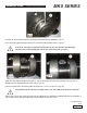
Block the rod using a clamp, and proceed with calibration using a torque wrench (1, fig. 40) as indicated
in paragraph 3. “SCREW CALIBRATION”
Insert the connecting rod in the plunger guide (1, fig. 36) and then insert the pin (1, fig. 35). Apply the
two seeger rings using the correct tool (1, fig. 34).
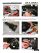
Make sure that conrods, plunger guides and wrist pins can move freely after being
assembled together.
Separate the caps from the connecting rod; correct coupling is guaranteed by the numbering on the side
(1, fig. 33).
After verifying the perfect cleaning of the crankcase, insert the connecting rod-plunger guide unit inside the
cylinders of the crankcase (1, fig. 32).
The insertion of the connecting rod-plunger guide unit inside crankcase must be done
by positioning the connecting rods with the numbering visible from above.
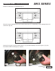
Block the three units using the correct tool, p/n F27566200(1, fig 31).
Pre-assemble the bearing, PTO side, on the shaft (1, fig. 41) and assemble the bearing on the opposite
side on the crankcase (1, fig. 42).
The bearing in fig. 42 has a tapered internal ring. Verify that the taper goes from the
outside towards the inside in order to allow the subsequent insertion of the sleeve.
Page 14
Ref 300699 Rev B
05-13