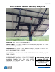
Page 1 of 12 UPM 12XHD, 12XHD Custom, 15X, 18X PIVOT CAP: 9 ¼“ O.D. 15” TALL PIPE SOCKET CENTER TUBE: 5” X 5” X 3/16”, LENGTH IS 52” (12XHD), 60” (15X) OR 5” X 5” X ¼” X 68” (18X) STEEL SQUARE TUBE CROSS PIECE: 3 ½“ X 3 ½“ X 3/16”, LENGTH IS 58” (12X, 15X) OR 3 ½” X 3 ½” X ¼” X 68” (18X), SQUARE TUBE – 2 PLACES LONGITUDINAL: 3” X 3” X 3/16”, LENGTH DEPENDENT ON MODULE USED, SQUARE TUBE – 2 PLACES ALUMINUM RAILS: 3” X 1 ½“ X 3/16” PUNCHED ALUMINUM ANGLE (12X) OR 3” X .13” X 1.
Page 2 of 12 Materials Box # Item Box #1 Pivot Cap, hardware bag #1 Box #2 Crosspiece (1 of 2) Box #3 Crosspiece (2 of 2) Box #4 Center tube, telestrut and telestrut bracket, winch and pulley, winch foundation and bracket, hardware bags #2-7 (for 12X HD Custom, 15X, 18X) and bag #8 (for 12X HD or 12XHD Custom with aluminum angle rails only, all others have aluminum channel rails and don’t require these brackets) Box #5 Longitudinal (1 of 2) Box #6 Longitudinal (2 of 2) Box #7 Box #8 Box #9 R
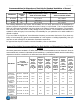
Page 3 of 12 Recommendations for Dimensions of Post Hole for Standard Installation of General Specialties Manufacturing Top of Pole Mounts Depth of Hole Width of Square Hole / Cubic Yards of concrete needed Diameter of Round Hole / Cubic Yards of concrete needed All 12XHD 85” 42” / 3.21 CY 52" / 3.86 CY All 15X All 18X 90” 96” 46” / 4 CY 46” / 4.35 CY 57” / 4.92 CY 57” / 5.
Page 4 of 12 UPM Model UPM12XHD Custom 8 Modules: 4 rails, 2 columns of 4 panels Standard stock tee socket size 8”, optional upgrade to 10” available UPM15X 12 Modules: 6 rails, 3 columns of 4 panels Standard stock tee socket size 8”, optional upgrade to 10” available UPM15X 10 Modules: 6 rails, 3 columns of 3,4,3 panels Standard stock tee socket size 8”, optional upgrade to 10” available UPM18X 15 Modules: 6 rails, 3 columns of 5 panels Standard stock tee socket size 8”, optional upgrade to 10” av
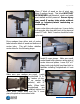
Page 5 of 12 Assembly Instructions UPM 12XHD, 15X, 18X Place pivot cap on top of steel post. Orient pivot bore with bronze bushings east and west. The 4 set bolt nuts should face south. Secure the pivot cap with ¾” square head set bolts. It is essential that you bolt the winch foundation/bracket to post approximately 1” below pivot cap. Use level to center foundation lugs plumb with center of pivot bore. Securely tighten bolts before installing winch. Bolt winch to foundation/bracket with 3 – ½” bolts.
Page 6 of 12 Place 4” block of wood on top of pivot cap. Keep 2 wedges handy. This block MUST NOT BE REMOVED until telestrut, winch and cable are installed and fully secured. Severe injury may result if center tube pivots without block or telestrut/winch restraining or controlling it! Lower center tube onto pivot cap. Line up holes in the center tube lugs with bore in the cap and insert 13” bolt. Note: 1 washer should be under nyloc nut.
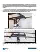
Page 7 of 12 Install the 2 ¼” x 2 ¼” end of telestrut between the lugs on the bottom of the pivot cap. Tighten the nyloc nut all the way. Bolt telestrut bracket to longitudinal with 3 ½” sq. u-bolts. The dimension between the “west” lug on the bracket and the inside of the cross piece for your specific mount can be found on the attached table. Insert 7/16” bolt through lugs and upper end of telestrut and tighten.
Page 8 of 12 Attach orange pulley to pad eye on telestrut bracket. Thread cable with quick link connector through pulley before closing pulley hanger with 3/8” bolt and nyloc nut. Now attach quick link to hole on left side of winch foundation (see attached Winch Detail). Fully tighten collar on quick link. Pull tension on cable as it comes off winch drum and cut zip ties. Take up slack in cable by turning winch handle while still holding tension on cable. This will prevent it from jamming in winch drum.
Page 9 of 12 Before proceeding, tighten 5/8” bolts at the end plates of center tube. Place 2 aluminum channels or angle on top of the longitudinals. Loosely attach 4 square u-bolts in holes provided at the bottom of the channels, or brackets for angles. Loosely place 2 PV panels on rail and attach to establish rail spacing. Center rails on longitudinals by equally measuring side to side to longitudinal ends. Then place the rest of the panels on the rails.
Page 10 of 12 Assembly of UPM 12XHD, 12XHD Custom, 15X, 18X Model Dimension between telestrut bracket lug and inside of cross piece UPM 12XHD 24 13/16” UPM 12XHD Custom 24 13/16” UPM 15X 28 13/16” UPM 18X 33 5/16” www.generalspecialtiesmfg.
Page 11 of 12 LONGITUDINAL STEP 1 Bolt winch to winch foundation with 3 – 3/8” grade 8 bolts – put flat washer on each side of winch/foundation interface. STEP 2 Attach red snatch block through “eye” in telestrut bracket. Before closing snatch block thread ¼” cable around sheave of pulley. Then attach quick link at end of cable to hole drilled in winch foundation. Tighten collar with a wrench. Asdfas Be sure to thread nylon nut on closure bolt for snatch block all the way down to end of threads.
Page 12 of 12 WARNING!!! Serious Injury or Property Damage may occur if array shifts while adjusting tilt angle without a safety line or winch attached and secured! DO NOT stand between post and lower side of the array while seasonally adjusting tilt angle. AND Use the winch you purchased with your mount, or tie a safety rope to top of array and wrap around car bumper or heavy permanent object to control adjustment of array.