User’s Handbook ENGINE IGNITION ANALYZER
Table of Contents 1. Safety Rules Page 1 2. Technical Specifications Page 2 2.1 General specifications Page 2 2.2 Electrical specifications Page 2 3. General description Page 3 3.1 Instrument description Page 3 3.2 Display description Page 3 4. Buttons, icons and menus operation Page 4 4.1 POWER/CLEAR button and menu Page 4 4.2 CYCLE button and menu Page 4 4.3 MODE button and menu Page 5 4.4 VIEW button and menu Page 5 4.5 HOLD button and menu Page 6 4.
2. TECHNICAL SPECIFICATIONS 2.1 General specifications Display: 3.5” TFT LCD, 320 x 240 pixels resolution. Frame rate: Up to 30 times per second. Ignition system comp.: Coil on plug, coil near plug, DIS, waste spark, conventional, and magneto. Engine cycle: 2 or 4 strokes. Power (internal): 3.2 volt/1500 mAh, rechargeable LiFePO4 battery. Auto power off: Automatically powers off after 3 min. of inactivity. Battery life: Approximately 6 hours of continuous operation.
3. GENERAL DESCRIPTION 3.1 Instrument description Micro USB connector BNC connector LCD display Protective hoster POWER/CLEAR button HOLD button CYCLES button VIEW button MODE button Fig. 1 - Instrument description 3.2 display description Engine cycle setting Mode setting Display setting Tachometer reading 01607 RPM Status indicators kv 20 Measurement display area 10 0 -10 -4 Page 3 -2 0 2 Fig.
4. BUTTONS, ICONS AND MENUS OPERATION 4.1 ‘POWER/CLEAR’ button • When the instrument is OFF, to turn it ON press and hold the ‘POWER/CLEAR’ button until the unit turns on (in approximately 1 second). • When the instrument is ON, to turn it OFF press and hold the “POWER/CLEAR’ button until the display turns OFF (in approximately 3 seconds). • When the instrument is ON, press the ‘POWER/CLEAR’ button to clear all measurement data, and start a new measurement.
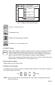
4.3 ‘MODE’ button and menu The ‘MODE’ button allows the selection of the type of measurement to be shown in the display. Upon pressing this button a pull down menu will open with the current setting highlighted, To change the setting press the ‘MODE’ button repeatedly until the desired setting is highlighted, then wait until the pull down menu closes. The new current setting will be displayed as the mode icon at the top of the screen.
01607 RPM kv Chart 20 Comparison 10 Digital 0 -10 -4 Waveform -2 0 2 ms Fig. 5 - Display mode selection menu Chart (i.e. trend line) view. Comparison view. Digital and analog gauge readouts. Waveform (i.e. oscilloscope) view. 4.5 ‘HOLD” button · When chart, digital or waveform display mode is selected, pressing the ‘HOLD’ button will pause the measurement, hold the current display, and the word “HOLD” will be shown in the measurement area of the display to indicate this status.
5. MEASURING MODES There are four different ignition system parameters that can be selected for measurement, depending on the engine’s ignition system: • Engine RPM. • Spark burn (firing) time. • Spark plug voltage. • Dwell angles (for ignition systems equipped with high voltage spark plug wires). • Primary ignition coil current ramp time (for coil on plug and coil near plug ignition systems). 5.
6. DISPLAY VIEWS There are four views that can be selected to display measurements: • Chart • Comparison • Digital • Waveform 6.1 Chart view This view displays the selected measurement’s value corresponding to each of the last 276 sparks, with the left most measurement being the oldest, and the rightmost the newest. The measurement scale and units are located on the vertical axis, at the far left of the display.
01607 RPM kv 15 Maximum 10 Average 5 Minimum 0 Oldest set Newest set Fig. 7 - Comparison mode display • ‘POWER/CLEAR’ button: Pressing the ‘POWER/CLEAR’ button clears all measurements, and re-scales the chart if necessary. • ‘MODE’ button: Pressing the ‘MODE’ button once will open the mode menu, and highlight the measurement mode currently selected; pressing the ‘MODE’ button again while the menu is open will select the next available measurement mode.
• ‘POWER/CLEAR’ button: Pressing the ‘POWER/CLEAR’ button clears all values in the graph, and re-scales the gauge if necessary. • ‘MODE’ button: Pressing the ‘MODE’ button once will open the mode menu, and highlight the measurement mode currently selected; pressing the ‘MODE’ button again while the menu is open will select the next available measurement mode.
7. MEASUREMENT PROCEDURES CAUTION To avoid personal injuries and damage to the instrument carefully inspect the spark plug wires, distributor cap, ignition coil , ignition module, and all other ignition system parts for damage or leaks, and avoid using this instrument in case any damage or leaks are found. Never touch the capacitive pick-up or flexible probe during a test.
COP pick-up Ignition module Fig. 11 - Using the COP pick-up on a ignition module 6- If the instrument is unable to detect the ignition system signal, it may be necessary to reposition the pick-up so that a consistent signal is detected and displayed. NOTES • The position of the pick-up and the particular design of the ignition module may affect the signal’s shape shown when the waveform display is selected.
NOTES • The absolute spark plug voltage reading will depend on the position of the pick-up, the particular characteristics of the wire, etc.. Therefore the placement of the pick-up relative to the wire should be keep as consistent as possible for all the measurements in order to compare voltage readings between several cylinders’ spark plug wires.
6- If the instrument is turned on (by pressing the ‘POWER/CLEAR’ button) at any time while connected to the power adapter, the instrument will display the charging status . 7- The USB type A connector can be also plugged into a USB port of a personal computer, powered USB hub, or any other USB compliant power source. 5- The recharge time will depend on the state of charge of the battery, and it may take up to 6 hours to fully recharge a depleted battery.
Part # GTC505MN1602EN To visit our website, scan the QR code below with your smart phone. Or type in your browser: www.gtc.ca #121 - 7350 72nd Street Tel: (604) 952-6699 Delta, BC Fax: (604) 952-6690 Canada V4G 1H9 email: info@gtc.ca © 2016 General Technologies Corp. Printed in Canada “SmarTach”, “V Ready”, “GTC505” and “GTC” are trademarks of General Technologies Corp.