
User Manual
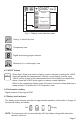


COPpick-up Ignitionmodule
Fig.11-UsingtheCOPpick-uponaignitionmodule
6-Iftheinstrumentisunabletodetecttheignitionsystemsignal,itmaybenecessaryto
repositionthepick-upsothataconsistentsignalisdetectedanddisplayed.
NOTES
• The position of the pick-up and the particular design of the ignition module may
affect the signal’s shape shown when the waveform display is selected. In order to
comparewaveformsbetweenseveralcylinders’ignitionmodules,theplacementofthe
pick-uprelativetotheignitionmoduleshouldbekeptasconsistentaspossibleforall
themeasurements.
•In some engines, the ignition modules are located very close together, and in rare
occasions this could cause the instrument’s pick-up to detect signals from nearby
modules,leadingtoinconsistentmeasurements.Thiscanusuallybesolvedbychanging
theplacementororientationofthepick-upontheignitionmodule.
7.3 Measuring ignition systems with (high voltage) spark plug wires
1-Ensuretheinstrumentisturnedoff.
2-InserttheSPWpick-upbarrelconnectorplugintotheexibleprobereceptacle,rst
removingtheCOPpick-upifnecessary.
3-Turn the instrument on, and select the appropriate cycle for the engine under
measurement.
4-Selectthedesiredmodeandview.
5-Placethesparkplugwireintotheslotofthepick-up,andasfaraspossiblefromother
sparkplugwirestryingtomaintainarightangle(90°)betweenthepick-upandthewire.
SparkplugwireSPWpick-up
Fig.12-UsingtheSPWpick-uponasparkplugwire
6-Iftheinstrumentisunabletodetecttheignitionsystemsignal,itmaybenecessaryto
repositionthepick-upsothataconsistentsignalisdetectedanddisplayed.
Page12