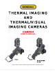
T HERMAL IMAGING AND THERMAL/VISUAL IMAGING CAMERAS CAMERA USER’S MANUAL G Ti 10 G Ti2 0 , G Ti3 0 , G Ti 50 Please read this manual carefully and thoroughly before using this product.
Sectional Overview What you should know and do to ensure your safety and avoid damaging the camera Read This First Illustrations and descriptions of all camera components and connectors Product Overview How to charge the battery pack; install the mini SD memory card; power the camera on and off; set the date and time; and select a language, TV standard and measurement unit Setup Instructions How to read the display; navigate menus; restore default settings Basic Functions How to make camera adjustme
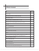
Table of Contents Read This First 5 What’s Included 7 Product Overview 8 8 9 Front View Keypad & Bottom View Setup Instructions 10 Charging the Battery Pack Installing the Battery Pack and Mini SD Card Powering On and Off Reading the Display Setting the Date and Time Local Settings Basic Functions 10 11 12 13 15 16 18 18 20 Selecting Menus and Settings Restoring Default Settings 21 Shooting Using the LCD Making Camera Adjustments Manual Focus Thermal, Visual and BiVision Image Displays BiVisi
55 56 Connecting to a Computer Using the Bluetooth Headset Troubleshooting Appendices 58 59 I. Using an Optional Lens 59 II. Camera Care and Maintenance 60 III.
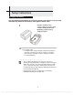
Read This First Practice Makes Perfect Before attempting to shoot important subjects, shoot several trial images to confirm that the thermal camera is operating correctly and that you know how to operate it correctly.
distortion of the thermal camera, fire, electrical shock or other hazards. Do not drop the batteries, place them near a heat source, directly expose them to flame, or immerse them in water Such exposure may damage the batteries and lead to leakage of corrosive liquids, fire, electric shock, explosion or serious injury. Do not attempt to disassemble, modify or apply heat to the batteries Any of the actions may cause an explosion.
What’s Included Item Quantity Thermal camera 1 Heavy-duty plastic protective case with shoulder strap 1 Compact battery charger 1 Rechargeable battery (1 installed in camera, 1 in case) 2 2GB Mini SD memory card with adaptor (pre-installed in camera) 1 Sun shield 1 Video cable with BNC plug 1 USB cable 1 Hand and neck straps (on camera) 1 Lens cap 1 CD containing: Reporting and analysis software (standard version); Software user’s 1 manual; Camera user’s manual; QuickS t a r t g uide,
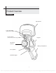
Product Overview Front View Flip-up LCD Torch (Flashlight) (GTi20, GTi30 and GTi50 only) Visual camera Keypad (GTi20, GTi30 and GTi50 only) IR camera and lens Battery compartment Laser pointer Definable trigger 8 PDF compression, OCR, web optimization using a watermarked evaluation copy of CVISION PDFCompressor
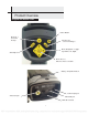
Product Overview Keypad and Bottom Views Power Button Menu up 1 level and Escape Save/Freeze screen and images Menu Navigation - Toggle Up, Down, Left, Right Auto Adjust Menu Access, Enter to choose selection Battery compartment latch Power input jack Video Out jack Mini USB jack Mini SD card slot 9 PDF compression, OCR, web optimization using a watermarked evaluation copy of CVISION PDFCompressor
Setup Instructions Charging the Battery Use the following procedures to charge the battery pack for the first time and subsequently when the low battery icon appears on the LCD. 1 2 Position a battery in the compact battery charger so the contacts nearly touch. Push the battery bat forward until it snaps into i place. Plug one end of the power cord into the charger and the other end into a 110VAC outlet. • The light on the charger will glow red while the battery is charging.
Setup Instructions Installing the Battery Pack and Mini SD Card Install the charged battery into the camera as follows: Release the battery compartment latch by pushing it down and forward. Lift and remove the battery compartment cover. 1 Align the battery’s edge with the line inside the compartment. Push the battery forward until it click-locks. Replace the battery compartment cover and latch it. 2 3 Replace the battery compartment cover.
Setup Instructions Powering On and Off The LED at the upper left of the keypad will be lit whenever the camera is powered on. To power on: Remove the lens cap and flip up the LCD to expose the keypad. 1 2 Press and hold the button for 3 seconds. • On the GTi10 and GTi20, the LED Button 3 at the upper left of the keypad will glow green. On the GTi30 and GTi50, the LED will toggle between green and blue, indicating that the camera is ready for a Bluetooth connection.
Setup Instructions Reading the Display The LCD’s frame is exactly the same size as the thermal camera’s field of view. The following information is available on-screen. Reading Max. temperature Upper limit color scale of Color scale Lower limit of color scale Time Battery charge Activate / Freeze Operation indicator Min. temperature Current emissivity setting Battery Status Symbols The following icons indicate battery status on the LCD.
About the operation indicator The operation indicator at the lower left of the LCD shows the current operating status of the camera. Camera status Camera operating status Menu Indicates operation in Menu Mode. Null Represents operation in a non-menu mode, with no analysis tools selected. SP1 9 Indicates that the current analysis tool is spot 1, spot 2 or up to spot 9. CAP. Indicates that the current analysis tool is auto-tracking spot.
Setup Instructions Setting the Date and Time If you intend to record images, you should set the Date and Time when powering ‘ON’ the thermal camera for the first time. 1 Make sure that the thermal camera is in Null mode (see p.14). 2 Press the MENU/ENTER button to call up the Main Menu. Then press the UP or DOWN key to navigate to the System Setup line. Press the MENU/ENTER button to open the System Setup menu.
Setup Instructions Local Settings Using this menu item, you can change the language of menus and messages, select either the NTSC or PAL TV standard, and choose metric or Imperial units for temperature and distance readouts. 1 Make sure that the thermal camera is in Null mode (see p.14). 2 Press the MENU/ENTER button to call up the Main Menu. Then press the UP or DOWN arrow to navigate to the System Setup line. Press the MENU/ENTER button to open the System Setup menu.
About Local Settings Language Video output Selects the language of the menus and messages. Sets the format of the video output of the camera to PAL or NTSC. Temp unit Choose °C or °F as the unit of temperature measurements. Distance unit Chooses meter or foot as the unit of distance measurements.
Basic Functions Selecting Menus and Settings You can select the settings by pressing the MENU/ENTER button. 1 2 1 Menu File Menu 2 Analysis Menu Press the MENU / ENTER button. Press the LEFT or RIGHT arrow. 3 Press the UP or DOWN arrow. 4 Press the MENU / ENTER button.
3 Select setting contents using 4 Change the settings using Exit Displayed menu items will vary according to the operation and setting contents. *The menu items may vary among different camera models.
Basic Functions Restoring Default Settings You can reset the menu and button operation settings to default. 1 Turn off the thermal camera. button 2 Press and hold the power button and the ESC button for three seconds. ESC button The data in storage will not be deleted when you reset the menu and button operation settings to default.
Shooting Using the LCD To use the LCD as your monitor for capturing thermal images, follow the instructions below. 1 Open the flip-up LCD screen 2 Using the trigger to turn on the laser pointer (see p. 46), aim the camera at a subject. 1. For the most-accurate temperature measurements, make sure the target appears in the middle of the LCD. 2. Closing the flip-up screen turns off the LCD and puts the camera to sleep.
Shooting Making Camera Adjustments Manual Focus 1 Point the thermal camera at the target. 2 Turn the focus ring until the target slips in and out of focus on the display. 3 Adjust the focus until the image is clearest.
Shooting Making Camera Adjustments Thermal, Visual and BiVision Image Displays The GTi20 and GTi30 thermal cameras can also record visual images using a built-in digital camera. The reason to capture a visual image is to use it as a reference for a thermal image. 1 Press the MENU/ENTER button. 2 Press the MENU/ENTER button to call up the Main Menu. Then press the UP or DOWN arrow to navigate to the IR/Visible line. Press the MENU/ENTER button to display the IR/Visible Setup menu.
Shooting About Fusion Displays In BiVision display mode, you can see thermal images ‘fuse’ into visible images. IR Only In this mode, you can use analysis tools to analyze the target. But what you see is the image with pseudo color. Vision Only In this mode, you see the visual image in full color. But you cannot use any analysis tools to analyze the target. BiVision In this mode, you see the visual image in the background with its thermal image ‘fused’ on it in the center square.
Shooting In BiVision display mode, you can move the fusion area using the arrow keys and see thermal images ‘fuse’ into visible images.
Shooting Making Camera Adjustments Making Image Adjustments You can adjust the level (brightness) and span (contrast) of thermal images manually or automatically. Auto Adjust The camera will automatically adjust the brightness, span or both parameters when you press the Auto Adjust button. How you set the Auto Adjust line of the Camera Setup menu (see p. 30) determines which of the three possible adjustments is made.
Shooting Making Camera Adjustments Making Manual Adjustments You can manually adjust the level and span of thermal images by using a menu or the arrow buttons. Use the UP and DOWN arrows to change the span (contrast) of an image and the LEFT and RIGHT arrows to change its level (brightness). Using the Manual adjust menu 1 Press the MENU/ENTER button to call up the Main Menu. 2 Press the UP or DOWN arrow to navigate to the Manual Adj. line.
Shooting Making Camera Adjustments Palette Settings 1 Press the MENU/ENTER button to open the Main Menu. 2 a) Press the UP or DOWN arrow to navigate to the Palette Setup line. Then press the MENU/ENTER button to open the Palette Setup menu. b) The default palette is Iron. Use the LEFT and RIGHT arrows to change the palette. The other options are Iron Inverted, Rainbow, Feather, Grey and Grey Inverted.
Shooting Making Camera Adjustments Image/camera Settings 1 Press the MENU/ENTER button to open the Main Menu. 2 Press the UP or DOWN arrow to navigate to the System Setup line. Then press the MENU/ENTER button to open the System Setup menu. 3 Press the UP or DOWN arrow to navigate to the Camera Setup line. Then press the MENU/ENTER button to open the Camera Setup menu. 4 Use the UP and DOWN arrows to select a parameter. a) Use the LEFT or RIGHT arrows to select IR Only, Vision Only, or BiVision.
Shooting Making Camera Adjustments About Image Settings Sets the function of the AUTO ADJUST button The camera will automatically adjust the level (brightness) and span (contrast) of the image to the optimum setting. The camera will automatically adjust the Level level (brightness) of the image. The camera will automatically adjust the Span span (contrast) of the image.
Shooting Making Camera Adjustments Freezing / Activating an Image You can activate/freeze a thermal image by configuring the trigger to do so. 1 Make sure that the thermal camera is in null mode (see p. 14). Press the MENU/ENTER button to open the Main Menu. 2 Press the UP or DOWN arrow to navigate to the Trigger Setup line. Then press the MENU/ENTER button to open the Trigger Setup menu. • Use the LEFT and RIGHT arrows to select Freeze/Live among the three options for the trigger.
Shooting Using Analysis Tools Changing Object/global Settings 1 Make sure that the thermal camera is in null mode (see p. 14). Press the MENU/ENTER button to open the Main Menu. 2 Press the UP or DOWN arrow to navigate to the Analysis line. Then press the MENU/ENTER button to open the Analysis menu. 3 Use the DOWN arrow to navigate down to the Object Para. line. Then press the MENU/ENTER button. 4 Set the analysis parameter.
About analysis parameters Object Emiss Distance Amb Temp Humidity Comp. Obj. Ref Temp Selects the object (a spot or area) whose parameters you wish to measure. Emissivity is a measure of an object’s reflectivity in the infrared spectrum. You can optimize the camera’s measurement accuracy for a specific object by entering its emissivity within the Analysis menu. Emissivity is a number with no units between 0 and 1. A table in the Appendix lists the emissivities of dozens of common materials.
Shooting Using Analysis Tools Setting Analysis Parameters 1 Make sure that the thermal camera is in null mode (see p. 14). Press the MENU/ENTER button to open the Main Menu. 2 Use the UP or DOWN arrow to navigate to the Analysis line. Then press the MENU/ENTER button to open the Analysis menu. 3 Use the UP or DOWN arrow to navigate to the Analysis Setup line. Then press the MENU/ENTER button. 4 Setting analysis parameters.
About analysis settings There are two kinds of temp-alert: Upper-limit alert and Lower-limit alert. Alerts 1.Upper-limit alert If you set the Alert line of the Analysis Setup menu to “on” and the Spot line of the Analysis menu to “Maximum”, the spot analysis tool "max sp10" will automatically capture the hottest spot within the screen.
Shooting Using Analysis Tools Setting Spot Analysis Parameters This section explains how to apply spot analysis tools to the thermal image. 1 Make sure that the thermal camera is in null mode (see p. 14). Press the MENU/ENTER button to open the Main Menu. 2 Press the UP or DOWN arrow to navigate to the Analysis line. Then press the MENU/ENTER button to open the Analysis menu. 3 Use the UP or DOWN arrow to navigate to the Spot line. Then press the MENU/ENTER button to open the Spot submenu.
4 Selecting a spot • • 5 Use the UP or DOWN arrow to select a spot, and then press the MENU/ ENTER button. Spot 10 will automatically track the hottest and coldest temperature spot within an area whose shape and size can be set by the user (see p. 45). Use the LEFT or RIGHT arrow to select the Maximum spot or Minimum spot. Moving the spot • • • Start from Step 1 to select a spot to analyze. Use the UP, DOWN, LEFT and RIGHT arrows to move the spot.
Shooting Using Analysis Tools Setting Area Analysis Parameters This section explains how to apply area analysis tools to the thermal image. 1 Make sure that the thermal camera is in null mode (see p. 14). Press the MENU/ENTER button to open the Main Menu. 2 Use the UP or DOWN arrow to navigate to the Analysis line. Then press the MENU/ENTER button to open the Analysis menu. 3 Use the UP or DOWN arrow to navigate to the Area line. Then press the MENU/ENTER button to open the Area submenu.
• If Area 5 is selected, its maximum, minimum and average temperatures will appear in separate boxes at the same time. 5 Moving the area. • Use Steps 1 through 4 to select an area. • Use the UP, DOWN, LEFT and RIGHT arrows to move the area. The temperature readout of the area changes in real time. Area No. Readings 6 Removing an area • • Use Steps 1 through 4 to select an area. Press and hold the ESC button to remove the area.
Shooting Using Analysis Tools Profile Analysis 1 Make sure that the camera is in null mode (see p. 14). Press the MENU/ENTER button to open the Main Menu. 2 Press the UP or DOWN arrow to navigate to the Analysis line. Then press the MENU/ENTER button to open the Analysis menu. 3 Use the UP or DOWN arrow to navigate to the Profile line. Then press the MENU/ENTER button to open a profile. 4 Moving a profile. • • Start from Step 1 to select profile analysis.
Shooting Using Analysis Tools Isotherm Analysis 1 Make sure that the camera is in null mode (see p. 14). Press the MENU/ENTER button to open the Main Menu. 2 Press the UP or DOWN arrow to navigate to the Analysis line. Then press the MENU/ENTER button to open the Analysis menu. 3 Use the UP or DOWN arrow to navigate to the Isotherm line, then press the MENU/ENTER key. Areas of concern will be highlighted in color. 4 Setting the isotherm range. • Start from Step 1 to set or select isotherm analysis.
Shooting Using Analysis Tools Removing Analysis Tools this This section explains how to remove analysis tools that you have activated. 1 Make sure that the camera is in null mode (see p. 14). Press the MENU/ENTER button to open the Main Menu. 2 Press the UP or DOWN arrow to navigate to the Analysis line. Then press the MENU/ENTER button to open the Analysis menu. 3 Use the UP and DOWN arrows to navigate to the Remove All line.
Shooting Saving Images You can save images in either of two ways: 1) by using a pulldown in the File menu or 2) by configuring the trigger to save files. Using the File menu to save files 1 Make sure that the camera is in null mode (see p. 14). Press the MENU/ENTER button to open the Main Menu. 2 The Main Menu will open with the File line highlighted. Press the MENU/ENTER button to open the File menu. 3 Use the UP or DOWN arrow to navigate to the Save line.
Shooting Using the trigger to save files 1 2 Make sure that the camera is in null mode (see p. 14) Press the MENU/ENTER button to open the Main Menu. Press the UP or DOWN arrow to navigate to the Trigger Setup line. Then press the MENU/ENTER button to open the Trigger Setup menu. 3 Use the LEFT or RIGHT arrow to select Save File. To use the trigger to save a file, squeeze the trigger and hold it for at least three seconds. The image will be saved in the current folder (see p.
Shooting Attaching Voice Memos to Images Voice recording You can attach a voice message of up to 30 seconds to any image (GTi30 only) 1 Install the Bluetooth headset (included with GTi30, optional for GTi10 and GTi20) using the instructions on p. 56 2 Freeze an image (p. 31), then press the MENU/ENTER button to open the Main Menu. 3 The Main Menu will open with the File line highlighted. Press the MENU/ENTER button to open the File menu. 4 Use the UP or DOWN arrow to navigate to the Voice Rec.
Shooting Configuring the Trigger By default, squeezing the trigger saves the current display as an image file. You can also configure the trigger to: Freeze/Activate an image 1. Press the MENU/ENTER button to open the Main Menu. 2. Press the or button to navigate to the Trigger Setup line. Then press the MENU/ENTER button to open the Trigger Setup Menu. 3. Use the or button to highlight Freeze/Live. Then press the MENU/ENTER button to save the selection. 4.
Playback and Erase Opening Images You can view and analyze saved images on the LCD monitor. 1 Make sure that the camera is in null mode (see p. 14). Press the MENU/ENTER button to open the Main Menu. 2 The Main Menu will open with the File line highlighted. Press the MENU/ENTER button to open the File menu. 3 The File menu will open with the Open line highlighted. Press the MENU/ENTER button. 4 Use the LEFT and RIGHT arrows to select an image. Then press the MENU/ENTER button to open it.
How to select an image 1 If you select Open or Delete in the File menu, a box like the one shown below will appear at the bottom left of the screen. File amount of current folder Serial number of current folder Serial number of current file 00001/00003/002/003
GZSAT001 Open SAT00001.SAT File count File Name 2 If the image you wish to open or delete is not in the current folder, use the LEFT and RIGHT arrows to browse for it. 3 To activate the image, press the SAVE/FREEZE button.Selecting a folder and filename 1 Make sure that the camera is in null mode (see p. 14). Press the MENU/ENTER button to open the Main Menu. 2 The Main Menu will open with the File line highlighted. Press the MENU/ENTER button to open the File menu. 3 Use the UP or DOWN arrow to navigate to the File Setup line. Then press the MENU/ENTER button to open the File Setup submenu. 4 The File Setup submenu will open with the Directory Name line highlighted.
Playback and Erase Playing Back Voice Memos To play back the voice messages you attach to images: 1 Install the Bluetooth headset (included with GTi30, optional for GTi10 and GTi20) using the instructions on p. 56. 2 Freeze an image (see p. 31), then press the MENU/ENTER button to open the Main Menu. 3 The Main Menu will open with the File line highlighted. Press the MENU/ENTER button to open the File submenu. 4 Use the DOWN arrow to navigate to the Voice Play line. Then press the MENU/ENTER button.
Playback and Erase Erasing Images Erased images cannot be recovered. Exercise caution before erasing an image. 1 Make sure that the camera is in null mode (see p. 14). Press the MENU/ENTER button to open the Main Menu. 2 The Main Menu will open with the File line highlighted. Press the MENU/ENTER button to open the File submenu. 3 Use the DOWN arrow to select the Delete line. Then press the MENU/ENTER button. 3 Select an image (see p. 48), and then press the MENU/ENTER button to delete it.
Uploading Images Images stored on the camera’s Mini SD memory card can be transferred via the included SD card reader to any computer with a USB port. 1 Swing the rubber cover on the bottom of the camera down to expose jacks and the mini SD card in its socket. 2 Lightly press on the Mini SD card with the tip of your finger and it will pop out. MiniSD card 3 Insert the card into the supplied SD card reader and plug the card reader into a USB port of your computer.
Camera Connections Charging the Battery Directly You can charge the battery directly using the optional power adaptor. 1 Swing the rubber cover on the bottom of the camera down to expose the power terminal on the right side. Insert the single-plug end of the power adaptor into the terminal. 2 3 4 Plug the other end of the adaptor into a 110VAC outlet. The LED on the camera’s keypad will flicker while the battery is charging.
Camera Connections Connecting to a TV Monitor You can increase the size of camera images that you view and analyze by using the supplied video cable to connect the camera to a TV or TV monitor. 1 2 Swing the rubber cover on the bottom of the camera down to expose the yellow Video Out jack. Insert the RCA mini-plug end of the supplied video cable into the jack.
Camera Connections Connecting to a Computer The camera's USB jack and included USB cable cannot be used to transfer stored images to a PC. To transfer images stored on the mini SD card: 1) eject the card, 2) plug it into the supplied SD card reader, and 3) insert the card reader into the USB port of a PC. This procedure is also described on p. 52. The camera's USB jack and cable can be used to stream live video to a PC. but only from a GTi30 or GTi50.
Camera Connections Using the Bluetooth Headset You can use the camera to capture, analyze and save thermal videos as well as thermal images. Doing so requires purchase of optional real-time software and use of the supplied USB cable. The controls for starting and stopping the recording of thermal video clips are on the software, rather than on the camera. A separate user’s manual for the software explains how to capture, save, and analyze thermal video clips.
5 6 After you have paired the camera and headset, the next time you want to use the headset, all you need do is turn it on. If the headset’s power LED is blinking blue, it is already paired and ready to use. Press the ESC and MENU/ENTER buttons at the same time to unpair the camera and the Bluetooth headpiece. ESC MENU/ENTER Put on the headset. You can use it to record (p. 45) or play back (p.50) voice memos now.
Troubleshooting Problem Camera will not operate Cause Power is not turned on Insufficient battery voltage Poor contact between camera and battery terminals Internal memory is full Camera will not save images Battery charge is used up quickly Battery will not charge Internal memory not formatted correctly Solution • Turn on the camera. See Powering On and Off (p.12). • Fully charge the battery. • Wipe the terminals with a clean, dry cloth.
Appendix I Using an Optional Lens Optional wide-angle and telephoto lenses for GTi series cameras are available from General. Whenever you install an optional lens, the camera will automatically configure itself to work with it. Each of the optional lenses--which are available with a 6.4o, 9o or 38o field of view for the GTi10, GTi20 and GTi30, and a 12o or 48o field of view for the GTi50--has an uncalibrated accuracy of ±3oF (±2oC) or ±4% of the reading, whichever is greater.
Appendix II Camera Care and Maintenance Use the following procedures to clean the camera body, lens, LCD monitor and other parts. Camera body Lens Wipe the body clean with soft cloth or an eyeglass lens wiper. First use a lens blower to remove loose dust and dirt. Then remove any remaining dirt by wiping the lens lightly with a soft cloth. • LCD Never use synthetic cleaners, paint thinners, benzene or water the camera body or lens. Use a lens blower brush to remove dust and dirt.
Appendix III Emissivity of Common Materials Material Temperature (°C Emissivity METALS Aluminum Polished aluminum Commercial aluminum foil Electrolytic chromeplate alumina Mild alumina Strong alumina 100 100 25 600 25 600 25 600 0.09 0.09 0.55 0.10 0.20 0.30 0.40 Brass Brass mirror (highly polished) Brass oxide 28 0.03 200 600 0.61 0.59 40 1090 0.08 0.36 100 25 800 1100 1080 1280 0.05 0.078 0.66 0.54 0.16 0.13 230 630 0.
Emissivities of Common Materials (Con’t) Material Temperature °C Emissivity Electrolytic ferric oxide Iron plate Cast iron, heavy ferric oxide Tempered iron, ferric oxide Melting surface Melting cast iron Melting mild steel Liquid steel Pure liquid iron 500 1200 925 1120 25 40 250 22 1300 1400 1600 1800 1500 1650 1515 1680 0.85 0.89 0.87 0.95 0.80 0.95 0.94 0.29 0.28 0.42 0.53 0.42 0.45 125 225 0.06 0.08 25 300 0.20 0.45 Magnesia Magnesia 275 825 900 1670 0.55 0.20 0.20 Hg 0 100 0.09 0.
Emissivities of Common Materials (Con’t) Temperature °C Emissivity Commercial tin plate 100 0.07 Strong oxidization 0 200 0.60 400 28 25 0.01 0.23 0.
Emissivities of Common Materials (Con’t) Material Temperature °C Emissivity ELECTRIC MATERIALS Epoxy glass plate Epoxy hydroxybenzene plate Gilded sheet copper Solder-coated copper Tin-coated lead wire Brass wires Block talcum terminal 0.86 0.80 0.30 0.35 0.28 0.87 0.88 0.
Specifications All specifications are based on General Tools & Instruments’ testing standards and are subject to change without notice.
Warranty Information General Tools & Instruments’ (General’s) GTi10, GTi20, GTi30 and GTi50 Thermal Imaging Cameras are warranted to the original purchaser to be free from defects in material and workmanship for a period of three years. Subject to certain restrictions, General will repair or replace this instrument if, after examination, the company determines it to be defective in material or workmanship.
THERMAL IMAGING AND THERMAL/VISUAL IMAGING CAMERAS SOFTWARE USER’S MANUAL GTi10 GTi20, GTi30, GTi50 Please read this manual carefully and thoroughly before using this product.
TABLE OF CONTENTS 1. INSTALLATION.......................................................................................................................... 4 1.1. System Requirement .............................................................................................................. 5 1.2. Install GTi IR Report .............................................................................................................. 5 1.3. Uninstall GTi IR Report ................................................
4.11. Play Folder............................................................................................................................ 33 4.12. Play Audio............................................................................................................................. 34 4.13. Copy to Clipboard................................................................................................................. 34 4.14. Property ...................................................................
11.4. Copy ..................................................................................................................................... 73 11.5. Paste ..................................................................................................................................... 74 12. VIEW .................................................................................................................................................... 74 12.1. Tile Horizontally ..............................
1. INSTALLATION 1.1. System Requirement XP: SP2 above Memory 512MB above CPU 700Hz above Framework 3.5 SP1 above Monitor Resolution 1024x768 above Computer Property setting: color quality 32bit Office 2003 above for generating report with WORD Vista: SP1 above Memory 1GB above CPU 1GHz above Framework 3.5above Monitor Resolution 1024x768 above Computer Property setting: color quality 32bit Office 2003 above for generating report with WORD Windows 7: Memory 1GB above CPU 1GHz above Framework 3.
Fig.1.2.2 Click Disk Cost button to ensure there is enough space on your selected drive, and then click OK button (see Fig. 1.2.4); Choose an installation hard drive and file path by clicking the Browse button or use the default driver and file path (see Fig. 1.2.3); Fig.1.2.
Fig. 1.2.4 Click the Next button to continue the installation or Back button to the previous step or Cancel button to terminate the installation (see Fig. 1.2.5); Fig.1.2.
Fig.1.2.6 Click the Close button to finish the installation (see Fig. 1.2.7). Fig.1.2.7 1.3. Uninstall GTi IR Report Click Start at the bottom left of the Windows’s desktop. Under the GTi IR Report of All Programs click Uninstall and following the instructions to remove the GTi IR Report software.
2. GETTING STARTED 2.1 Launch Application There are two simple ways you can launch the program. Click Start at the bottom left of the Windows’s desktop and under the GTi IR of the All Programs select GTi IR Report. You can also simply double click the GTi IR Report icon on your Windows Desktop. Note: For PRO, USB, NET, or ALL version, user must plug a registered dongle associated with the software onto the computer or input the “Activation Code” into the following register window.
get the Activation Code from your vendor, please input the Activation Code into the register window. You can always activate your license from menu Help -> Activate in the GTi IR Report later. And then click OK button. The software will retrieve version information from the activation code (e.g. ALL version). A version in green characters indicates an official version, while other versions in red indicate trial versions. 2.
3.2. Shortcuts You can select shortcut to do thermal image analysis; You can right click in the shortcut area to show or hide specified shortcuts.
3.3. Analysis Mode You can click Analysis tab on the left to enter into analysis mode. When the mouse’s cursor moves to tab area on the left, the file explorer will be displayed automatically. When the mouse’s cursor moves out of the file explorer area, the file explorer will be hidden automatically. You can click Analysis Info tab on the right to view analysis information. 3.4. Report Mode You can click Report tab on the left to enter into the report mode.
(2)Select menu View => Analysis, it will show a tab page of Analysis in left side. Please select a folder in Folder Tree and then it will show a thumbnail list beside the Folder Tree (press Ctrl to select multiple images). User can open images in following ways: A、Right click on the thumbnail image, and select the menu Open; B、Double click the thumbnail – image; C、Drag and drop the thumbnail image into right analysis area. 4.1.2.
SAT file (*SAT) : List SAT files only. Optical light and IR files(*SAT;*CCD) : List SAT and CCD files.
Recording File(*SAR;*SAZ) General IR File(*JPG;*BMP) : List SAR or SAZ files. The type is available in USB, NET, and ALL versions. : List JPG or BMP files with or without temperature data. Template File(*IRW ;*IRT;*IRWX; *IRTX) : List Analysis Working Template (IRW/IRWX) or Report Template (IRT/IRTX) files. The type is available in PRO, USB, NET, and ALL versions; Optical File(*CCD;*JPG;*BMP) : List optical image files or JPG and BMP with or without temperature data files.
Temp Filter Set a temperature range as a file open filter, which only opens thermal images in which temperature value falls into a specified temperature range. Action: select menu File => Open, check the option box Temp Filter. Examples: Open thermal image file(s) in which the temperatures is between 40 and 60 degree Celsius.
Open thermal image file(s) in which the temperature is not within 40 and 60oC. Action: select menu File => Open => choose the option box Temp Filter => select Out of Temp range => enter min and max temp value => select being opened thermal images => click Open button.
Open thermal image file(s) in which the temperature is great than or equal to 60 degree Celsius. Action: select menu File => Open => choose the option box Temp Filter => select ≥ Upper Temp => enter a temp value => select being opened thermal images => click Open button.
Display isothermal area in opened image Display isothermal area of specified temperature range in green color. Temp Label When Max Temp, Min Temp, Cursor Temp and/or Center Temp checkbox is selected, the opened images will show selected label(s). Tool Templates When Tool Templates checkbox is selected, it means that thermal images or recording files will be opened with the same tools as that of selected *.ird file.
Right click on the thermal image window, select Save Tool Template menu Select a saving path, input a file name and then click Save button.
Select Tool Templates checkbox in the Open file window, and click file(*.ird). button to select a Select thermal image or video file(s) and then click Open button. All selected thermal files will be opened with the selected template file.
Show Tool Info If you select Show Tool Info checkbox, you can open JPG or BMP files with saved tools. Otherwise, the opened JPG or BMP files do not include tools.. Open Associated Files You can open a series of files (only in SAT and CCD format) with associate name in the same folder.
For example, Enter associated file name (“69”) and being opened file number(“3”) in following window. Open one file with the associated name, for example “69085523.SAT”, then there are three name associated files opened. Image Adjusting Select Auto or Manual image adjusting mode to be used for thermal file open. Show invalid temp checkbox indicates whether show invalid temp area or not in the opened files. Please see detail in 5.3 Image Adjusting.
Palette Select a palette for the opened files’ palette. 4.2. Save All In the report mode, you can save all contents as IRT/DOC/PDF files. Action: menu File => Save All or click Save All shortcut =>select a saving folder in file explorer=>click OK button=> then you will find the saved files in the selected folder. You can change saving format in system settings: 4.3.
4.4. Save Report Template In the report mode, you can save the current formatted contents except Fusion / Image Merging/ Image Subtraction windows into a reporting template file (.irt). The template can be used to generate batch report that uses selected thermal image(s) to replace image(s) in the template to form analysis reports.
4.5. Save As 4.5.1. SAT Save As Action: menu File => Save As => SAT Save As or click Save As shortcut =>specify saving object (Current or All), saving file type, saving path, whether save analysis data or not => Click Save button Choose the Current means to save the current thermal image into a file; Choose the All means to save all thermal images in Analysis or on the Report tab page(s) into files. You can specify a file type (*.jpg or *.bmp).
4.5.2. CCD Save AS Save opened image(s) as specified format (jpg or bmp) file(s). Action: menu File => Save As => CCD Save As => specify saving object, file type, path and file name => Click OK. Click Cancel to abort the operation. 4.5.3. SAR Save AS For the USB, NET or ALL version, save opened recording file(s) as specified format (AVI or MPG) file(s). Action: menu File => Save As => SAR Save As => specify saving object, file type, path, file name and whether save analysis data or not => Click OK.
4.5.4. IRW Save As For PROversion, save all images of the current Analysis window into an IRW file with specified name. Action: menu File => Save As => IRW Save As => specify saving file path and file name => Click OK. Click Cancel to abort the operation. 4.5.5. IRT Save As For the PROversion, save the current report template into IRT file. Action: menu File => Save As => IRT Save As => specify saving file path, file type and file name => Click OK. Click Cancel to abort the operation.
4.5.6. Temporary window save as Save the fusion, merging or image subtraction temporary window into JPG/BMP file. Action: right click on temporary window=> select Save As in popup menu. 4.6. Close Current Image Close the current image in the analysis and report mode. Action: select menu File => Close Current Image or click the shortcut 4.7. Close All Images Close all images in the analysis and report mode.
4.8. Close Current Sheet Close Current Sheet will close the current report template in the report mode. Action: select menu File => Close Current Sheet or click the IRT file close icon 4.9. Close All Sheets Close All Sheets will close all opened report templates in the report mode Action: select menu File => Close All Sheets or click all IRT file close icons one by one. 4.10. Tools Select a tool for thermal analysis. Action: select menu Tools => Tool 4.10.1.
4.10.4. Point Click the shortcut to begin plotting point(s) on a thermal image. Click the shortcut right click mouse on the thermal image to end the drawing function. again or 4.10.5. Line Click the shortcut to begin drawing line(s) on a thermal image. To end the drawing function, click the shortcut again or right click mouse. Note: after click line shortcut, if you press Shift button while drawing line, you will draw up a horizontal line or diagonal line or vertical line. 4.10.6.
4.10.9. Polygon Click the shortcut to begin plotting polygon(s) on a thermal image, single clicking to complete the edges of a polygon and finally double clicking to complete the last edge and close the polygon. You can click the shortcut again or right click mouse to end the drawing function. 4.10.10. Changes Place cursor on a tool (e.g. point, line, circle, rectangle, polygon, or poly-line) to resize it or change its location when no tool shortcut is selected or clicked.
4.10.11. Delete Tool Click the shortcut shape ( Point, and use the cursor to select tool. When the cursor is changed to a deleting Line, Circle, Rectangle, your mouse to remove the tool. Click the shortcut Polygon, Poly-line), left click a second time to end the deleting operation. 4.10.12. Delete All Tool Right click mouse on a thermal image and click Delete All Tool from the popup menu, which allows you to remove all tool on the image at once.
4.12. Play Audio Listen to voice record in a thermal image file. If the thermal image does not have voice record, the shortcut is disabled. Action: menu Tools => Play Audio or click the Play Audio shortcut 4.13. Copy to Clipboard Copy the current image or chart into system’s clipboard so you can paste the image into other applications such as Word document. Action: menu Tools or right click mouse on a thermal image => Copy to Clipboard 4.14.
4.15. Rename In analysis and report mode, user can rename opened thermal images, recording files and CCD images. Action: right click opened thermal images, recording files and CCD images => select menu Rename=> input a new file name in the following box=> click OK button. Note: the original file name in the system path also alters together.
4.16. Data Export Export temperature values of a selected thermal image in a matrix of rows and columns into Txt,CSV, or Microsoft Excel format file. You can specify a temperature range, which export data will be blank if a temperature value is out of the temperature range. Note: A file in CSV format can be opened by a text edit tool and Microsoft Excel. Exporting data into CSV file is much faster than into Excel file. Therefore, using CSV file for data export is recommended.
(3) Select saving path: click browse button , select a path from the window, input a file name and select a file type. Finally, click Save button. 5. IR IMAGE SETTINGS 5.1. Palette The system provides seven palettes and their reversed settings. You can check the Reverse box to get a complementary palette scheme. For the PROversion, you can specify a palette for an individual tool area (e.g. circle, rectangle, and polygon).
5.2. Image Adjusting Action: menu Image => Image Settings => Image Adjusting or click Image Adjusting shortcut or right click on a thermal image=> Image Settings =>Image Adjusting The image adjustment can highlight or detail certain parts of the thermal image. You can specify a temperature value range of the current image as a color mapping span. If the temperature values of the image fall outside this range, they will be mapped to either upper or lower end of the palette.
Area Adjusting : Right click mouse on a selected tool area (e.g. circle, rectangle, or polygon) and click Area Adjusting from the popup menu. Right click mouse on a selected tool area and click Area Adjusting again to remove the area adjusting. 5.4. Isothermal Area Paint an image’s pixels with a selected color to denote temperatures within a specified temperature range. You can specify up to 16 isothermal areas. You can specify Transparent to make isothermal area more visible.
5.5. Temp Parameters Set parameters of temperature calculation for a thermal image. For the PROversion, you can set parameters for a selected tool area. Action: menu Image=> Image Settings=> Temp Parameters or right click on thermal image=> Image Settings or click shortcut .
5.6. Temp Label Action: menu Image or right click on a thermal image=> Image Settings => Temp Label or click shortcut You can set labels with temperature value, coordinates, and color for the maximum temperature point, minimum temperature point, or/and cursor point of a thermal image by checking or unchecking option boxes. Temp Diff : show value difference of maximum or minimum temperatures between two tool areas. If Show Energy Value is checked it will show energy value of above selected item(s) as well.
Reference Temp: give a criteria (reference) temperature value to calculate a relative temperature against the real one. For example, The opened thermal image max temp is 46.15℃(without setting reference temp). If you set reference temp as 10℃, then you can see relative max temp 36.15℃ shown on the thermal image. User can select menu Tool=>Temp label=>Max temp or click the shortcut temperature.
User can select menu Tool=>Temp label=>Min temp or click the shortcut temperature. User can select menu Tool=>Temp label=>Cursor temp or click the shortcut at cursor. to show min to show temperature 5.7. Show spot information Click icon to show spot information in IR image. 5.8. Clear Temp Difference Label Clear all temperature difference label in thermal image. Action: right click on one area and select menu Clear Temp Difference Label from popup menu. 5.9.
5.10. Temp Range For the USB or NET or ALL version, you can select a calibrated temperature range for calculation. When the temperature range change, system will also send a command through RS232, USB or Ethernet to change IR camera’s temperature measurement range (Please check IR camera’s user manual to see if your IR camera has switching temperature range function).
6. ANALYSIS CHART 6.1. Distribution Display distribution of temperatures of a selected line or ploy-line on a thermal image. The following picture shows temperature distribution charts of line L1 with a vernier. If a vernier is on a line like L1, you can move the vernier to see temperature value and coordinate of vernier position. You also can view changes of the distribution by moving a line or poly-line.
Left click and hold mouse button at a point of the distribution chart; Move mouse cursor to left or right of shown red line to select a range that appears in yellow; Release the mouse button, the selected range of distribution or partial distribution will be shown; You can repeat above steps to zoom in the distribution. You can click minus circle at lower left corner of the chart to zoom out the partial distribution. 6.2.
You can click minus circle at lower left corner of the chart to zoom out the partial trend. 6.3. Ratio Chart Users can generate frequency chart of temperature range in IR image or specified tool area (for example circle, rectangle, or polygon). Action: select menu Tools=>Analysis Chart=>Ratio Chart or right click mouse on a thermal image =>Analysis Chart=> Ratio Chart or click the shortcut . X coordinate indicates temperature in area; Y coordinate indicates percentage of temperature.
You can click minus circle at lower left corner of the chart to zoom out the partial ratio. 6.4. 3D Distribution Show the current distribution in a three dimension view. X and Y axis indicate pixel position, Z axis indicates temperature value. Action: select menu Tools=>Analysis Chart=>3D Distribution or right click mouse on a thermal image =>Analysis Chart=> 3D Distribution or click the shortcut . 6.5.
Note: multiple lines and/or polylines can be connected in one distribution or trend chart; multiple circles, rectangles and polygons can be generated in one ratio or trend chart. For example: Draw line L1 and L2 on a thermal image and generate distribution of L1 first. Right click on L1 distribution and select menu Data Connection. Add L2 in the left folder to the right list. Click OK button. There will be a distribution of L1 and L2. Note: It is the same as ratio chart or trend.
For recording file or real time monitor, users also can export trend data. You can right click on Trend chart and select Start Export Data to begin data export. And right click on the Trend chart and select Stop Export Data to end of data export. When stop data export, you can specify a file name to store exported data. The export data is saved in the csv/ xls format that can be opened by text edit tool or Microsoft Excel.
Select Spline Range style, highlight max and min temperature in the chart.
3D gap depth setting: Graphics symbol setting: 52 PDF compression, OCR, web optimization using a watermarked evaluation copy of CVISION PDFCompressor
Label setting: Forecasting setting( for trend or partial tend only): 7. IMAGE PROCESS 7.1. Image Switch In the analysis or report mode, you can replace the current thermal image with another thermal image by right clicking on it and select “Image Switch” or select menu Tools=> Image Switch. This feature is useful for analyzing different thermal images with the same set of analysis tools. Only can the same type of IR camera files or records be switched one another. Thermal image (*.
For example, 7.2. Fusion The fusion function allows you to blend an optical image (BMP, CCD, or JPG) with an infrared image, which can assist in identifying objects of infrared images. Set saving style and format in System Settings before fusion: select menu System => Settings, there are three saving style: 1) Auto Save—save the fusion image in default saving path automatically.
Steps of making fusion (for example, select Only Display): (1) Open a thermal image (.sat file) with a polyline and an optical image (.bmp, .ccd, or jpg file).
(4) Click the Ok button; (5) Adjust size of the optical image window to make its object matching thermal image’s object; (6) Move or change the thermal image size to match the object of the optical image; 56 PDF compression, OCR, web optimization using a watermarked evaluation copy of CVISION PDFCompressor
(7) Adjust the blending CCD ratio by moving the scroll bar button; (8) Select fusion type: A. Select IR Image: IR image is fused with CCD file that is without tool. B、 Select Area (also user can add tools for fusion, for example, add a rectangle in the following window); and then click OK button, the result is that only tools be fused with CCD. C、 Select Isotherm, and select a isothermal area in the palette. Click OK button.
D. Save CCD Save CCD which is not fused with thermal image. Action: select the option box Save CCD. 7.3. Snapshot You can take a snapshot on the current frame of a recording file and save it as a new image file in SAT, BMP, or JPG format. Set file saving style and format in System Settings before snapshot: select menu System => Settings, there are three saving style: 1) Auto Save—save the snapshot image in default saving path automatically.
Steps of snapshot ( for example, select Prompt to Save): 1. Move mouse cursor onto the recording file and left click mouse to select it as current thermal image; 2. 3. 4. 5. Click the shortcut ; Choose file type (.bmp, .jpg, or .sat) and file path ; Give a file name; Click the Save button. 7.4. Merging For the PROversion, adjoin specified thermal image and/or area into one thermal image.
Merging steps: (1) Open 4 thermal images, select menu Image => Image Merging or click image merging shortcut , right click on each thermal image and select menu Add into Merging Window from popup menu to add all thermal images into merging window: (2) Click OK button.
(3) Click Save button, and open saved merging image: 7.5. Image Subtraction For PROversion, calculate difference of temperature value for each point at the same location of two thermal images and generate a temperature difference image. Image subtraction can be used to analyze temperature changes of the same view of thermal images that is taken at different time.
do temperature analysis on the saved image; 2) Prompt to Save—pop up a Save As window to prompt user for saving: input file name and file type. You can do temperature analysis on the saved image; 3) Only Display—do not save subtraction image and only display temporary window on which you cannot do temperature analysis. Action: menu Image => Image Subtraction (or click image shortcut => Ok or Apply.
(1)IR image subtraction (2)Tool subtraction Draw one circle and one rectangle on each thermal image.
Select tool object and its image object 7.6. Zoom In Enlarge the current thermal image(*.sat), recording file(*.sar), or optical file(*.ccd, *.jpg, *.bmp) . . Also you can use mouse to drag Action: menu Action => Zoom in or click the Zoom in shortcut edge of a image or input the ratio from 50% to 300% in the following textbox directly to change its size. 7.7. Zoom Out Reduce size of the current thermal image(*.sat), recording file(*.sar), or optical file(*.ccd, *.jpg, *.bmp) .
Action: menu Action => Zoom out or click the Zoom out shortcut . Also you can use mouse to drag edge of a image or input the ratio from 50% to 300% in the following textbox to change its size. 7.8. Original Size Restore the current thermal image (*.sat), recording file(*.sar), or optical file(*.ccd, *.jpg, *.bmp) to original size. Action: menu Action => Original Size or click the Original Size shortcut ratio 100% in the text box to the original size. . Also you can input the 7.9.
Action: right click mouse on a thermal image => 3D or select menu Image=>3D 8. REPORT 8.1. Load data from analysis mode to report mode In report mode, you can load all analysis data( static images, charts) into report mode. Action: right click on blank page, select menu Load data of analysis mode from popup menu. Load thermal image and its analysis data(tools or charts) into report mode by clicking the checkbox in left window. Load CCD image into report mode by clicking the checkbox in right window.
8.2. New Clicking the shortcut or selecting menu Report => New enters report mode. Report mode allows you to generate a report and/or template in an default paper size template area through adding thermal images, CCD images (.ccd, .jpg, and .bmp format), analysis results, text comments, and so on. You can right click and select page operation function to add or delete a page and open multiple template areas by clicking the shortcut .
Click the button on the right of the display IRT file or select menu File => Close All Sheets to close the report mode. 8.3. Grid Settings Right click on blank report page.
8.4. Save Report Template or Save Report You can save the current template to an IRT format file which is used in batch report by selecting “Save Report Template” in File menu, or save it to Word or PDF format file by clicking the save report shortcut . 8.5. Batch Report For the PRO, USB, or NET version, user can select a report template and multiple thermal images to generate Word/PDF format reports or new report templates (.irt).
Choose thermal image methods: search thermal images (.SAT or .JPG/BMP with thermal data file) from file browse of left side, select thumbnails of thermal image files by clicking check box. The program uses the selected thermal images in one-by-one order to replace thermal images in the template. When the last thermal image is replaced, a new page or report will be generated. If residue is less than the number of images in the template, the rest thermal images in the template will keep unchanged.
o Add Fixed Format Data – add selected analysis data of a specified IR image into the table. You can choose types of the analysis results. Fixed format data cannot be edited by users manually. 8.9. V iew Matching In report mode, arrange associated thermal image and CCD file which are used to being replaced by another thermal image with CCD file of the same name in batch report.
(3) Click OK button, there will be a dual vision window 8.10. Print Preview Under report mode, preview format of the current report before printing. Action: menu Report =>Print Preview 8.11. Print Under report mode, send the current report to printer directly. Action: menu Report=> Print 9. OPEN RECENT Show recent opened images, CCD images, IRT files, IRW files, recording files and so on. Action: menu File => Open Recent 10. EXIT Exit the program. Action: select menu File => Exit. 11. EDIT 11.1.
11.3. Cut In report mode, cut the current image or chart into system’s clipboard so you can paste the image into the report template. Action: Use drag mouse to select images you want to cut. The selected objects (e.g. images, tables, text boxes) are grouped with green borders, click Cut shortcut green boxes with Cut in popup menu; or right click mouse outside of the 11.4. Copy In report mode, copy the current image or chart into system’s clipboard so you can paste the image into the report template.
11.5. Paste In report mode, paste the copied or cut image or chart into specified position. Action: Add a page or move to a page that you want to paste, click Paste shortcut click mouse outside of the green boxes with Paste in popup menu; or right 12. VIEW You can check or uncheck these following menus under View.
12.1. T ile Horizontally In analysis mode, all opened windows are arranged in a line from left to right. There are three arrangement modes: name, modified time and default. Action: select menu View=> Horizontal. 12.2. T ile Vertically In analysis mode, all opened windows are arranged in a line from up to down. There are three arrangement modes: name, modified time and default. Action: select menu View=> Vertical.
12.3. Cascade In analysis mode, all opened windows are arranged in a line from inner to outer. There are three arrangement modes: name, modified time and default. Action: select menu View=> Cascade.
12.4. Full Screen Maximize the window of thermal image, optical image and recording file. Action: right click on the image and select Full Screen from the popup menu. 12.5. Analysis and Analysis Info Click Analysis tab to enter into analysis mode, where you can do all image analysis settings. Click Analysis Info tab to enter into analysis information page, where show information of all opened thermal images. For example, there is analysis information of two thermal images and tool shown on the right side.
12.7. System Info For the PROversion, click System Info tab to display all opened images (including tools) and report information. 12.8. File Convert For the PROversion, convert selected thermal images of SAT format to JPG/ BMP files with or without temperature data or batch convert thermal images under a specified folder.
(1)Convert single or multiple thermal image(s) Select File Convert option box=> select a folder in file explorer=> select the thermal thumbnails in right side=> select conversion type=>click OK button=> new generated file(s) is(are) saved in the specified path.
(2)Batch convert folder Select Batch Folder Convert option box=> click browse button (Fig.12.8.1) to select a folder (Fig.12.8.2)for being converted(Fig.12.8.1)=> click OK button=> all new generated files are saved under the original folder(Fig.12.8.3). Fig.12.8.1 Fig.12.8.
Fig.12.8.3 12.9. File Edit For the PROversion, you can concatenate thermal recording files and/or delete selected images to generate a new recording file. (1) Drag and drop the recording thumbnail into bottom blank area (2) You can manually select frames for being deleted, for example, select frame 1,2,3,3,4,5,6,7,8,9,10 seperately. If the frames are continuous, you can check the option box Frame Selection and input the initiate and end frame.
(3) Select a saving path of the edited recording by click Browse button and then click OK button; (4) Open the new recording file, you will find the selected frames be missed. 12.10. Search Action: select menu View => Search For PROversion, in Analysis or Report or File Convert or File Edit mode click search shortcut . Input file name or file type or file shooting time or file temp range and then click Search button. User can manually stop searching by clicking Stop button.
You can check the option box Default as USB Connection, and next time you will connect USB directly according to before USB connection settings by clicking the shortcut . Note: You only can connect one USB camera at one time. 13.2. NET Connect For the NET or ALL version, through Ethernet to connect one or multiple Net IR cameras, perform real time monitor and analysis of thermal image. Note: See IR camera manual about Ethernet connection.
13.3. Monitoring Screen Start recording manually Stop recording manually Snapshot current real time image Recording settings (please see 13.5 Recording Settings) Lock level/span value of palette to identify the current frame temperture Unlock level/span value of palette to show real time level/span value Create NUC (please see 13.6 NUC Calibration) Select NUC (please see 13.6 NUC Calibration) Change dataload.
Focus out Focus in Auto focus 13.4. Real T ime Recording Settings Action: click the shortcut in real time recording window Note:recording speed depends on computer processing power. 13.4.1. Fixed-Length Recording It can record in a specified length of time. Action: You should specify a length of recording time and recording speed(maximum speed is 25). Set temperature parameters and adding record notes. Select Save Tool option box indicates save tool while recording.
Recording Cycle: periodic time of single recording which includes interval. Recording Time: real time of single recording There are additional settings: changing temperature parameters and adding record notes. Save Tool option box indicates save tool while recording. There is a default saving path in system, you can change the path by clicking Browse button to select a new path.
13.4.4. Manual Recording You can manually start recording by clicking the icon and end recording by clicking the icon at any time in Manual mode. Set Speed, temperature parameters and recording notes as the following screen shot. Save Tool option box indicates save tool while recording. There is a default saving path in system, you can change the path by clicking Browse button to select a new path.
13.4.5. Custom Recording In Custom Recording mode, you can specify the initial time of recording and the total recording time. Click Add button to add current time and default recording time (10 seconds) that you can edit by double click on them. Set Speed, temperature parameters and recording notes as the following screen shot. Save Tool option box indicates save tool while recording. There is a default saving path in system, you can change the path by clicking Browse button to select a new path.
13.5. Play Recording Open a recording file and click Play button. Play recording file; Pause playing recording file; Go to the initial point of recording file; Go to the finial point of recording file; Play recording file backward (you should press the icon for about 5 seconds); Play recording file fastward(you should press the icon for about 5 seconds); Play recording file in single-step; Play recording file in loop; Play recording file settings (they are active only for the file recorded in V2.
(3) Select Time: input initial time, click Ok button, and it starts playing recording file at specified initial time. 13.6. Non-Uniformity Correction The camera shows a blue ball in the middle of the IR-Image and this can be seen in both the display as well as in the screen of the pc and also in videos. Therefore, if you want to record after connecting the camera to PC, you need to do NUC calibration. (1) Please click the following icon “Create NUC” 90 .
Please cover the IR lens with a smooth surface material such as a thick white paper before input the file name and file path. (2) Take away the covering material and click the following icon “Select NUC” . Please open the NUC you saved in (2). The result is that you can see the “blue ball” has disappeared and the video shows a uniform picture.
14. SYSTEM 14.1. Languages Allow user to select an available language for the application interface. Action: menu System => Language. For example, select English: 14.2. Temp Scale Select the Celsius, Fahrenheit or Kelvin temperature scale. Action: menu System => Temperature Scale. 14.3. Custom Palette For PROversion, user can add or delete palette into the software. Action: menu System => Custom Palette. (1) Delete Palette Select a palette (for example, Custom1) and then click Delete.
(2) Add Palette Input the custom palette name in the textbox, for example, “Custom Palette2”, and then click on the color row to add a specified color. 14.4. Emissivity Allow user to manage emission data used for temperature calculation.
14.5. System Settings Set default values for the application. 14.5.1. File (1) Saving Style Auto Save: after click Save button, snapshot file/merging file/ fusion file/image subtraction file will be saved in specified path automatically. Prompt to Save: after click Save button, system will pop up a saving window where user should select a saving path and input saving file name of snapshot file/merging file/ fusion file/image subtraction file.
(3)Saving File Path Specifies default file path of snapshot/ merging/ fusion/ image subtraction files Note: the default saving file path is active only when user selects auto save mode. 14.5.2. Tool Set tool parameters: Tool font settings—font size, font style and font color settings. Border settings—border size and border color settings. Tool settings——set whether show tool max temp, min temp, distribution, ratio chart, trend or not.
14.5.3. Image Set default values for opened thermal image. Palette setting---Set palette for opened thermal image. Image Adjusting——Set adjusting mode for opened thermal image.
14.5.4. Parameters Set default initial parameters of temperature calculation for a thermal image opened or tool drew. 14.5.5. Report Page size—set default page size of IRT Orientation—set report page orientation: vertical or horizontal.
Saving format setting—set initial format of saving report template. 14.5.6.
15. HELP 15.1. Content Select menu Help=> Content or press F1 on the keyboard to display manual file. 15.2. About Display software version information and company information.
15.3. Active Upgrade the software of trial version to that of official version. Action: menu Help=> Active=> input received Activation Code=> click OK button. 16. VERSION COMPARISION FEATURE Open thermal image and optical file(*SAT;*CCD *JPG; *BMP ) Open recording file(*SAR) Open IRW file/ report template file(*IRW, *IRT) Save IRW file Save report template Save tool template(*IRD) Save all IRW save as IRT save as *.PDF * .DOC file SAT save as*.JPG *.BMP file CC D save as .JPG *.BMP file SAR save as *.
FEATURE Delete tool Tool settings Play audio Copy to the clipboard Open recent Temp parameters (IR image) Temp parameters (area) Temp label (IR image) Temp label (area) Notes Clear temp diff Switch temp range Distribution Ratio chart Trend Analysis settings/data export 3D distribution Temp data export of thermal image or temporary window Temp data export of thermal image area Temp data export of recording file Palette of thermal image Palette of area Custom palette Isothermal area of thermal image Isotherma
FEATURE Batch report Report edit (arrow line, text box, table, print, print preview) Cut/copy/paste/undo/redo Tile horizontally/tile vertically/cascade View adjusting Full screen File Convert File edit USB connect NET connect Record Languages Temp scale Custom emissivity System settings Exit Help 102 STD √ √ √ √ √ √ √ √ √ √ PRO √ √ √ √ √ √ √ √ √ √ √ √ √ √ √ √ √ PDF compression, OCR, web optimization using a watermarked evaluation copy of CVISION PDFCompressor
103 PDF compression, OCR, web optimization using a watermarked evaluation copy of CVISION PDFCompressor
General Tools & Instruments 80 White Street New York, NY 10013 212-431-6100 Manual # GTi Software Manual 010112012 (GTi10, GTi20, GTi30, GTi50 Software User’s Manual) GTi is a trademark of General Tools & Instruments, LLC. Copyright © 2012 General Tools & Instruments, LLC. All rights reserved.