The PalmScope™ COMPACT RUGGED VIDEO INSPECTION SYSTEM USER’S MANUAL PCS55 Please read this manual carefully and thoroughly before using this product.
TABLE OF CONTENTS Introduction . . . . . . . . . . . . 3 – 4 Key Features . . . . . . . . . . . . . . . 5 Safety Instructions . . . . . . . 5 – 6 What’s in the Package . . . . 5 – 6 Product Overview . . . . . . . . 6 – 9 Setup Instructions . . . . . . 9 – 16 Install Batteries . . . . . . . . . . . 9 Prepare the Probe . . . . 10– 15 Attach Thread Protector or Accessory . . . . . . . 15 – 16 Operating Instructions . . 16 – 18 Quick Start Procedure . 16 – 18 Specifications . . . . . . . . . . . . .
INTRODUCTION Thank you for purchasing General Tools & Instruments’ PCS55 Compact Rugged Video Inspection System (The PalmScope™). Please read this user’s manual carefully and thoroughly before using the instrument. The PalmScope is more than just the smallest full-featured video inspection system available today. It is also built to survive in the harsh environments of plumbing and automotive maintenance and repair—not to mention any unusual situations a do-it-yourselfer might subject it to.
Other general automotive applications include inspecting hard-to-reach or hard-to-see areas of the engine compartment or undercarriage. The PalmScope has only five control buttons (power on/off, brightness up, brightness down, video zoom, and video flip), making it very easy to learn to use. Video within the probe’s field of view is displayed on a high-quality 2.4 in. (61mm) diagonal color LCD. The video zoom and flip functions make The PalmScope an even more valuable inspection tool.
KEY FEATURES • Fits in your pocket or clips to your belt • Probe coils inside case for storage • Drop-proof from height of 1m (39 in.) • Long, flexible-obedient probe with 9mm diameter camera head penetrates tight, hard-to-reach spaces • 2.7 in.
Never use the system to perform medical inspections. WHAT’S IN THE PACKAGE The PalmScope and its accessories come in a blister pack. In addition to the instrument, the package contains: • A plastic bag containing the four probe tip accessories: the 45° mirror, pickup hook, magnetic pickup, and thread protector • A nylon pouch with a belt clip • This user’s manual PRODUCT OVERVIEW Fig. 1 shows The PalmScope and its accessories. Fig. 2 shows the positions of its display, controls and physical structures.
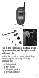
Fig. 1. The PalmScope, the four probe tip accessories, and the nylon pouch with belt clip Inside the pouch is a small plastic bag containing the following probe tip accessories: A. Pickup hook B. 45° mirror C. Magnetic pickup D.
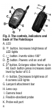
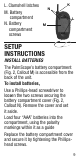
Fig. 2. The controls, indicators and back of The PalmScope A. LCD B. button. Increases brightness of LED lights C. button. Inverts video 180° D. button. Powers unit on and off E. button. Enlarges video frame up to 4X. Each button press increases zoom level by factor of 0.5 F. button. Decreases brightness of 4 camera LED lights G. Lanyard attachment bar H. Lens cap I. Camera head J. Flexible-obedient probe K.
L. Clamshell latches M. Battery compartment N. Battery compartment screws K N L M SETUP INSTRUCTIONS INSTALL BATTERIES The PalmScope’s battery compartment (Fig. 2, Callout M) is accessible from the back of the unit. To install batteries, Use a Phillips-head screwdriver to loosen the two screws securing the battery compartment cover (Fig. 2, Callout N). Remove the cover and set it aside.
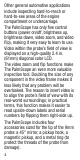
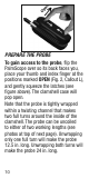
PREPARE THE PROBE To gain access to the probe, flip the PalmScope over so its back faces you, place your thumb and index finger at the positions marked OPEN (Fig. 2, Callout L), and gently squeeze the latches (see figure above). The clamshell case will pop open. Note that the probe is tightly wrapped within a twisting channel that makes two full turns around the inside of the clamshell. The probe can be uncoiled to either of two working lengths (see photos at top of next page).
Each length incurs a tradeoff of probe reach vs. probe rigidity. A longer probe is obviously better for inspecting distant objects. But when uncoiled to its maximum length of 24 in., the probe sags from its own weight, preventing it from being extended horizontally. If the 12.5 in. length is sufficient to reach most of your inspection targets, select that shorter length; at 12.5 in., the probe is light enough at 12.5 in. long to be extended horizontally.
To re-coil the probe, begin by holding the unit in front of you as shown in the first photo of the sequence below. Take care that the lanyard does not accidentally get tangled up with the probe as you coil it. If you chose the shorter probe length, you will not have to wrap the unextended probe section at all. All you must do is make sure to wrap that section within the part of the internal channel nearer the front of the unit.
Before squeezing the two halves of the clamshell together to close it, check that the entire length of the probe section inside the clamshell is within the channel and that the camera head (the thicker end of the probe) is within both semicircular sections of the top of the housing comprising the probe’s exit port (Fig. 2, Callout K). Finally, squeeze the two halves of the clamshell together to close it. The clamshell is not properly closed until you hear the latches snap.
For this reason it is especially important that the probe is wrapped tightly and remains within the helical channel without “crossing over” the channel boundaries. Before squeezing the two halves of the clamshell together to close it, check that the entire probe is within the channel and that the camera head is within both semicircular sections of the exit port. Finally, squeeze the two halves of the clamshell together to close it.
clamshell is not properly closed until you hear the latches snap. It’s important to note that when recoiling the probe from either its short or long extended length, you must wrap it very tightly within the channel. If the camera head has not cleared the probe exit port as you finish wrapping the probe (see photo at right), you will not be able to squeeze the clamshell shut. You must start over.
• The magnetic pickup lets you retrieve lost or dropped metal objects—nuts and bolts, for example—located by the probe. • The thread protector keeps the camera head and its threads from being scratched or damaged by anything the probe bumps into. Attach the thread protector before you use The PalmScope for the first time. Remove it before attaching any of the three other accessories. Reattach the thread protector after removing an accessory.
3. Press and hold the button (Fig. 2, Callout D) for at least 3 seconds to power on the unit and illuminate the LCD. 4. Point the camera-tipped end of the probe at the target of interest, pushing the probe through holes or bending the probe around objects if necessary. Avoid bending the delicate probe excessively; this will damage it. 5. Press the button (Fig. 2, Callout B) to increase the brightness of the camera’s LEDs 6. Press the button (Fig. 2, Callout F) to decrease the LEDs’ brightness 7.
bottom right of the screen. Push the button several times to zoom in closer at a level of 2.0X, 2.5X, 3.0X, 3.5X and 4.0X. The next push of the button reverts to normal size (1X) viewing. To power off The PalmScope, press and hold the button for at least 3 seconds. The PalmScope is designed to be powered for several hours by the same set of four “AAA” batteries. A (low battery) icon will appear on-screen when the total battery charge drops below an operational threshold.
SPECIFICATIONS Display Size/Type: 2.7 in. (686mm) diagonal TFT color LCD Display Resolution: 320 x 240 pixels Monitor Controls: 180° flip, 1X to 4X zoom in 6 steps, brightness + and – Camera Head Diameter: 9mm (0.35 in.) Probe Length & Type: 2 ft. (0.6m) flexible-obedient Camera Field of View: 60° Camera Depth of Field: 1 in. (25mm) to 10 ft. (25mm to 3m) Camera Light Source: 4 adjustablebrightness white LEDs Impact Resistance: From height of 1m (39 in.
MAINTENANCE TIPS • The camera at the tip of the probe is a sensitive, sophisticated device. Do not use the probe as a hammer or to clear debris. • Do not insert or bend the probe by force. Over-bending any section of the probe to a radius of less than 2 in. (50mm) many permanently damage delicate internal cables. • Remember to power off The PalmScope after each inspection session. • Do not get water on the LCD.
WARRANTY INFORMATION General Tools & Instruments’ (General’s) PCS55 (The PalmScope) Compact Rugged Video Inspection System is warranted to the original purchaser to be free from defects in material and workmanship for a period of one year. Subject to certain restrictions, General will repair or replace this instrument if, after examination, the company determines it to be defective in material or workmanship. The warranty period begins on the date of purchase.
Acceptance of the exclusive repair and replacement remedies described herein is a condition of the contract for purchase of this product. In no event shall General be liable for any incidental, special, consequential or punitive damages, or for any cost, attorneys’ fees, expenses, or losses alleged to be a consequence of damage due to failure of, or defect in any product including, but not limited to, any claims for loss of profits. Register now at www.generaltools.
prepaid freight to the attention of our Service Center at this address: General Tools & Instruments 80 White Street New York, NY 10013 212-431-6100 Remember to include a copy of your proof of purchase, your return address, and your phone number and/or e-mail address.
GENERAL TOOLS & INSTRUMENTS 80 White Street New York, NY 10013-3567 PHONE (212) 431-6100 FAX (212) 431-6499 TOLL FREE (800) 697-8665 e-mail: sales@generaltools.com www.generaltools.com PCS55 User’s Manual Specifications subject to change without notice ©2013 GENERAL TOOLS & INSTRUMENTS NOTICE - WE ARE NOT RESPONSIBLE FOR TYPOGRAPHICAL ERRORS.