Elite Steam Residential Steam Humidifiers User manual
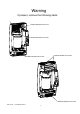
Warning If present, remove the following items: LATCH THE CYLINDER CLAMP REMOVE BEFORE INSTALLING REMOVE BEFORE INSTALLING REMOVE BEFORE INSTALLING REMOVE BEFORE INSTALLING REMOVE BEFORE INSTALLING Elite Steam +03U221903 REV 2.
IMPORTANT WARNINGS We wish to save you time and money! We can assure you that the thorough reading of this manual will guarantee correct installation and safe use of the product described. BEFORE INSTALLING OR HANDLING THE HUMIDIFIER PLEASE CAREFULLY READ AND FOLLOW THE INSTRUCTIONS AND SAFETY STANDARDS DESCRIBED IN THIS MANUAL AND ON THE LABELS ATTACHED TO THE Elite Steam.
Elite Steam +03U221903 REV 2.
Contents 1. HOW THE ELITE STEAM WORKS 1.1 Basic Operation....................................................................................................................... 1.2 Cylinder Life ....................................................................................................................... 1.3 Calculating Humidity Load ............................................................................................... 2. MODELS 6 6 7 7 8 3. INSTALLATION 9 3.1 Positioning.............
1. How The Elite Steam Works 1.1 Basic Operation Elite Steam is an electrode humidifier. It produces steam for humidification by passing electric current through the water between metal electrodes in the plastic steam generator cylinder. There are no heating elements. Steam output is directly proportional to the conductivity of the water, and the amount of electrode immersed in the water.
1.2 Cylinder Life 1.2.1 Basics of the Steam Cylinder The Steam Cylinder is the engine of the humidifier. As the humidifier operates and water is evaporated and minerals are left behind. Much of these minerals are removed through the cylinder drain. Some are deposited on the walls of the cylinder and the cylinder electrodes. When a lower section of the electrodes develop a thick coating, the water level is raised to expose clean electrode surface.
2. MODELS There are two basic models available in two voltages. Duct models require selection of an additional kit. Duct Steam Injection Fig.2.a PART NUMBER Room Steam Discharge MODEL LIST DESCRIPTION Fig.2.b PARTS INCLUDED RS 15 Fig. 2.b Room steam dicharge, 15 gallons per day (5.5 Lbs per hour) 115-120v Complete Humidifier. E2 humidistat, code valve, water fill connector, water supply tubing. RS 35 Fig. 2.
3. INSTALL ATION Duct Steam Injection 3.1 Positioning B A The Elite Steam has been designed for wall mounting and, since it is an atmosheric steam humidifier, should be placed close to the point where the steam will be used, to minimize the steam hose length (and the amount of condensate). Certain clearances must be maintained around the unit for safety and maintenance. C F E 3.2 Mounting Fig. 3.a D 3.2.
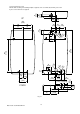
24 [7/8] 40 [1 5/8] 3.2.2 Fastening to the wall Drill the wall according to the drilling template supplied; then secure Elite Steam firmly to the wall by the screws and anchors supplied. UP 54 [21/8] 256 [10 /18] 65 69 48 [21/2] [1 7/8 ] [2 3/4 ] 128 [5] 60 [2 3/8] 128 [5] 9 [3/8] 30 ø 1/8] [1 0 ø4 5/8] [1 448 [17 5/8] 600 [23 5/8] 70 [2 3/4] ø [7/ 23 [7 ø 2 8] /8] 3 50 [2] 0 ø5 [2] 61 [2 3/8] 94 [3 5/8] 115 [41/2] 35 [1 3/8] 37 53 78 [31/8] [11/2] [21/8] 62 [21/2] DOWN 10 2 [4] Fig.
3. INSTALL ATION Duct Steam Injection 3.1 Positioning B A The Elite Steam has been designed for wall mounting and, since it is an atmosheric steam humidifier, should be placed close to the point where the steam will be used, to minimize the steam hose length (and the amount of condensate). Certain clearances must be maintained around the unit for safety and maintenance. C F E 3.2 Mounting Fig. 3.a D 3.2.
3.4 Steam distribution Millimeters Inch 31.5 mm 1.24” 50 mm 1.96” 56 mm 2.20” 57.5mm 2.26” 100 mm 3.93” Ø22mm Ø 0.31” Ø22 mm Ø 0.86” Ø22mm Ø 1.18” 12or 22mm 0.47”or 0.87” Steam inlet Condensate drain Steam inlet Condensate drain Flange gasket End support Mounting screw A B C D E F G H I 1 2 3 4 5 6 7 3.4.1 Duct steam injection The maximum allowed duct static pressure is 2 in WC. The Duct Mount Kit includes a plastic duct injection nozzle. See Fig.3.
IMPORTANT: Maximum length of rubber steam hose is 4m (12 feet.). Insulated copper tubing may be up to 6m(20feet) in length. In all cases, minimize sharp bends and elbows. Use 2- 45° elbows instead of 90°s. Hose inner diameter = 7/8” (22 mm). Hose outer diameter = 1-1/4” (30 mm). 1,5 m (5 FTmax.) IF NO TRAP ≥5° 3 m (10 FTmax.) WITH TRAP ≥5° 1,5 m (5 FTmax.) IF NO SLOPE 0,9 m (3 FTmax.) ≥15° DR AINS TYPICAL INSTALLATION WHEN THE UNIT IS ABOVE THE DISTRIBUTOR PIPE 3 m (1 0 FTmax.) 1,5 m (5 FTmax.
3.5 Power wiring Check that the power supply voltage to be connected matches the value indicated on the rating plate inside the electrical panel. L1 Insert the power and ground connection cables into the electrical panel compartment using the strain reliefs supplied, and connect to the terminals. An external fused disconnect must be installed. See Fig. 3.o L2 All wiring must be in accordance with local, state and national electric codes. Fig. 3.p Fig. 3.
3.6.1 Connect the E2 Humidistat for On/Off Operation: 1. Remove the humidistat from the base, squeeze the louvered base at the top and bottom. To remove the humidistat from the wall, lift up on the humidistat and pivot top away from wall. 2. Before wall mounting, please remove the black foam gasket. 3. Before return air duct mounting, please remove the breakout piece. 4. If return air duct mounting, route wires between humidistat and base. 5. Mount the sensor outside the house.
3.7 Wiring Connections: Terminals L1-L2 -GROUND KEY N1-GND-N2 AB-AB Functions Power supply and Ground connections Programming port NTC air proving sensor Remote enabling input IN-GND Control signal imput NC-C-NO NC alarm contact Common alarm contact NO alarm contact External fan relay Power for external humidistat NO-C 24-GND Electrical specifications Power supply 110 VAC 1-phase 50-60Hz 1.86kW or 230VAC 1-phase 50-60Hz 4.
4. START -UP IMPORTANT WARNINGS: 1. Before starting, check that the humidifier is in perfect condition, that there are no water leaks and that the electrical parts are dry; 2. Do not connect power if the humidifier is damaged or even partially wet! When installation is completed, flush the supply pipe for around 10 minutes by piping water directly into the drain, without sending it into the humidifier; this will eliminate any scale or residues that may cause foam when boiling. 4.
5. OPERATING ELITE STEAM 5.1 Displaying Information By pressing the “Reset” button for 2 seconds, the display will loop from amperage to production in % of the maximum production to the hour counter and back to amperage: Fig. 5.a 1. Amperage: the value of the current that flows through the water making it boil off (default display) 2. Production %: the current production expressed as a percentage of the capacity . 3.
5.5 Using the E2 Humidistat Press to select OFF, MANUAL or AUTO mode (if outdoor sensor is. connected) OFF mode: The humidifier is turned off. MANUAL mode: The E2 will work to maintain the single humidity selected. You can set your desired humidity level by pressing or . The humidifier will turn ON or OFF according to your manual setting. (The humidifier will operate when the measured relative humidity falls more than 2% below the set point).
6. TROUBLE SHOOTING Problem Causes The humidifier does not 1 No electrical power 2. On/off switch of the humidifier in turn on Position 0 (off) 3. Control connectors improperly connected 4 . Blown fuses 5. Transformer failure Solutions 1. Check the safety devices upstream from the humidifier and the presence of power 2. Close the switch on the panel: position I 3. Check that connectors are properly inserted in terminal block 4. Check the condition of fuses 5.
7. M AIN TENANCE 7.1 Periodic checks • After one hour of operation: Check that there are no significant water leaks. • Every fifteen days or no more than 300 operating hours: Check operation, that there are no significant water leaks and the general condition of the cylinder. Check that during operation there is no arcing between the electrodes. • Every three months or no more than 1000 operating hours: Check operation, that there are no significant water leaks and, if necessary, replace the cylinder.
5 7.3 Replacement Parts 12 12 4 6 10 2 1 11 3 13 7 8 14 9 12 Item 1 2 2 3 4 4 5 6 7 7 8 8 9 10 11 11 12 13 13 14 Part No.
Continued from page 22 7500 7501 7512 7513 7521 7522 7526 7531 7527 7517 7528 7525 7545 7540 7016 7078 1 1 1 1 7523 7524 7543 7516 7552 20-1 STEAM NOZZLE 20-4 FILL CONNECTOR 20-3 CONDENSATE HOSE 5/16" I.D. 20-2 STEAM HOSE 7/8” ID. 22 MM I.D. PER FOOT DP030D22RU 12" STAINLESS STEEL DISTRIBUTION MANIFOLD DP045D22R0 17.
8. TECHNICAL SPECIFICATIONS Instant steam production; voltage-phase-frequency, kW Outlet pressure limits (Pa) Dimensions (mm ) Weight empty/packaged/ installed with water IP class Electrode power cables Power relays Ground connection Input water type Conductivity range Water fill connection Water fill - instant flow Drain connection Drain water temp Drain flow Embedded fan flow Serial communication Notes 2.5 kg/h (5.5 lbs/hr): 110 VAC 1-phase 50-60 Hz, 1.86 kW 5.
Elite Steam +03U221903 REV 2.
NOTES Elite Steam +03U221903 REV 2.
Elite Steam +03U221903 REV 2.
GENERAL FILTERS, INC. Agency: 43800 GRAND RIVER AVE. NOVI, MICHIGAN 48375-1115 Form 35-5 Rev 2.0 WWW.GENERALAIRE.COM CANADIAN GENERAL FILTERS, LTD. 39 CROCKFORD BLVD. SCARBOROUGH, ONTARIO M1R3B7 WWW.CGFPRODUCTS.COM Elite Steam +03U221903 REV 2.