
Use and Care Manual


English
10" Drill Press
Operator’s Manual GDP1012A
10
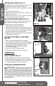
SETTING DRILL DEPTH (FIG 13)
The drill depth scale (18) is located on the hub (A4). See FIG 13. The
scale pointer (A5) indicates the spindle travel distance.
To stop the drill at a specific depth for consistent and repetitive
drilling:
1. Loosen the depth scale lock (A6)
2. Rotate the scale hub (A4) until pointer (A5) is aligned to the
desired depth on the scale.
3. Tighten the depth scale lock (A6). The chuck will stop after
traveling downward to the distance selected.
ADJUSTING RETURN SPRING (FIG 14)
The return spring is adjusted at the factory and should not need
further adjustment. If adjustment is deemed necessary:
1. Unplug the machine from the power source.
2. Loose the two jam nuts (A7). Do not remove.
3. Firmly hold the coil spring cover (A8). Pull out the cover and
rotate until the pin (A9) on the return spring plate engages the
next notch in the cover. Turn the cover clockwise to decrease
tension and counterclockwise to increase tension.
4. Tighten two jam nuts. Do not over-tighten. The jam nuts should
be tightened against each other.
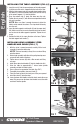
SQUARING THE TABLE TO THE HEAD
(FIG 15)
1. Install a 3" long drill bit into the chuck (4) and tighten.
2. Raise and lock the table (8) about 1" from the end of the drill bit.
3. Place a combination square on the table as shown. The drill bit
should be parallel to the straight edge of the square.
4. If an adjustment is needed, loosen the bevel lock bolt
(B4-FIG 12 ) with a wrench.
5. Square the table to the bit by tilting the table.
6. Tighten the bevel lock bolt (B4-FIG 12) when square.
OPERATION
ON/OFF SWITCH (FIG 16)
1. To turn the tool ON, move the switch (3) to the"ON" position.
2. To turn the tool OFF, move the switch (3) to the "OFF" position.
3. To lock the switch in the OFF position, remove the yellow safety
key from the switch. Store the key in a safe place.
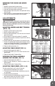
INSTALLING OR REMOVING BITS
WARNING: To reduce the risk of injury, only
use the chuck key provided with this drill press or a
duplicate of it. This chuck key is self-ejecting and will
“pop” out of the chuck when you let go. This action is
designed to help prevent throwing of the chuck key
from the chuck when power is turned “ON”. Do not
use any other key as a substitute; order a new one if
damaged or lost.
FIG 16
3
SAFETY
KEY
FIG 15
8
4
FIG 14
A9
A8
A7
FIG 13
A6
A5
18
A4