GEnicom 5000 Series Programmer’s Manual GEK – 00031B
Table of Contents Page Chapter 1.Introduction.................................................................... 8 overview of printer emulation...............................................................8 Control Codes......................................................................................8 Escape Sequences ...............................................................................8 CSI and OSC .......................................................................................
Table of Contents Page Chapter 2. ANSI Emulation (Continued) ANSI 4800/4410 Strap 1 OUT ........................................................ 46 ANSI 4800/4410 Strap 1 IN ........................................................... 46 Setting Bar Code Parameters .......................................................... 47 Bar Code Dimensions .................................................................. 48 Default Bar Code Characteristics .................................................
Table of Contents Page Chapter 3.Printronix P300/P600 Emulation .................................. 66 Introduction ......................................................................................66 Control Codes....................................................................................66 Printronix Graphics ...........................................................................69 Dot Patterns and Densities..............................................................69 Dot Patterns ....
Table of Contents Page Chapter 4.Printronix P-Series Emulation (Continued) Postnet Bar codes (SFCC |p*xxxxx-yyyy-zz*) .............................. 104 Ribbon Minder Enable/Disable (SFCC r E/SFCC r D) ................ 104 Ribbon Minder Set Job Rate (SFCC r J nnnn E) ......................... 104 Ribbon Minder Worn Message (SFCC r A n)................................ 104 Command Line Debug..................................................................... 105 Font Styles, Pitches, and Character Sets ...
Table of Contents Page Chapter 6.Epson FX286-e Emulation (Continued) Miscellaneous Commands ...............................................................149 FX-286e Dot Graphics .....................................................................150 Specifying Graphics Line Length ...................................................150 Image Data Bytes ..........................................................................151 Graphics Programming Example ..............................................
Table of Contents Page Chapter 8.PPL3 Plus Emulation (Continued) Printable Area............................................................................ 253 Positioning and Movement............................................................ 253 Horizontal Advance Increments .................................................... 254 Fixed HAI................................................................................... 254 SIXEL GRAPHICS ..............................................................
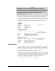
CHAPTER 1. INTRODUCTION OVERVIEW OF PRINTER EMULATION Commands are sent to the printer in the form of control codes and escape sequences. These differ from normal data to be printed in that they give instructions to the printer on paper movement, style of print, size, density, and many other selectable features. Certain protocols are needed so that the printer can recognize and act on these commands sent from the host.
NOTE The physical spaces in the escape sequences shown in this publication are only for clarification purposes and are not used in the actual string. If a space is actually needed in the sequence, it will be shown as an in the mnemonic form of the sequence. In the decimal form, it will appear as a 32, and in the hexadecimal form, as 20.
LINE TERMINATORS Some control codes and escape sequences act as line terminators. Line terminators cause all data received since the last terminator to be printed. Without a terminator, data will remain buffered. DECIPOINTS Throughout this manual decipoints are used as a unit of measure. A decipoint equals 1/720th of an inch and is used as a standard of measurement for parameters associated with set distances. A few examples are margins, tabs, and vertical paper movements.
CHAPTER 2. ANSI EMULATION CONTROL CODE AND ESCAPE SEQUENCE ACTIVITY LEVELS ANSI control codes and escape sequences are assigned activity levels depending on which print mode is currently active. The following charts provide information on what to expect from the control codes and escape sequences in each printing mode. I-IGNORED No noticeable effect on printing will occur. V-VALID These sequences do not affect the printing mode in progress, but take effect when normal printing resumes.
Control Code Activity Levels Control Code BEL Chapter 2.
Escape Sequence Activity Levels Escape Sequence DCS (Graphics) Font Load GEK-00029B Line Terminator No A Dot Graphics I Bar Codes I A I I Normal No Oversize POSTNET A I A I GENBCS No A A A A I GENFD No A A A A I GENGRM No A V A A I GENHTS No A A A A I GENOSM No A V V A I GENSLR No A A A A I GENSNC No A V V Note 2 I GENSPM No A V A A A GENTST Yes A A I A I GENVFU Yes A A A A I DENVTS No A A A A I GSM No A V V A
CONTROL CODE DEFINITIONS BEL Bell (07H): Receipt of a BEL code causes the beeper to sound for approximately 1/2 second after any preceding printable data has been processed. BS Back Space (08H): Line terminator. The paper position remains unchanged and the print position is moved left one character space from the current. If the print position is at the left margin, no action is taken. CR Carriage Return (0DH): Line terminator.
FF Form Feed (0CH): Line terminator. The paper is advanced to the next top-of-form position. When the EVFU is enabled and programmed, paper will advance to the next stop in channel 1. NOTE An option strap from the CCU Control Panel Menu using the SETUP/FORMAT/MODIFY FORMAT/GENPRTOPTS selection can disable this feature. HT Horizontal Tab (09H): Advances the print position to the next horizontal tab location.
ESCAPE SEQUENCE DIRECTORY Sequence Meaning CSI or ESC [ Control Sequence Introducer 19 CSI p1 p2 SP ~ GENEMU: Selects emulation 21 ESC [p1 ; p2 SP B GSM: Modifies vertical (p1) and horizontal (p2) character size 31 ESC [p1 ; p2 SP G SPI: Sets lpi (p1) and/or cpi (p2) in decipoints 32 ESC H HTS: Sets a tab at current print position 30 ESC J VTS: Sets a tab at current paper position 28 ESC K PLD: Moves print line down 3/72 inch (subscript) 25 ESC L PLU: Moves print line up 3/72 inch (s
Sequence Meaning ESC [ p1;… pn u GENHTS: Sets horizontal tabs (p1, etc.) in decipoints or columns 30 ESC [ p1 ;… p12;v GENVTS: Sets vertical tabs (p1, etc.) in decipoints or lines 30 ESC [ p1 x GENSNC: Selects international character sets 22 ESC [ p1 ; ...
ANSI ESCAPE SEQUENCE CATEGORIES The ANSI escape sequences have been separated according to functionality. Special areas of interest, such as graphics and the electronic vertical format unit (EVFU), have been described in separate sections. The functional groups are: Chapter 2.
Housekeeping Sequences ESC [ CSI (Control Sequence Introducer): This sequence is used to begin sequences, that generally have multiple parameters. ESC ] OSC (Operating System Command): This is another special sequence introducer. Sequences which begin with OSC require the ST string terminator sequence (ESC \) to end them. ESC \ ST (String Terminator): Terminates the loading of EVFU tables, download fonts, and dot graphics strings.
ESC Q GENTST (Self-Test): This sequence is ignored. Decimal: Hex: BASIC: Chapter 2.
CSI p1 p2 SP ~ GENEMU (Emulation Control): Switches the control of the printer to another emulation. The parameters in the sequence are defined as follows: p1 Emulation identifier. This parameter selects the particular emulation by a reference number supplied by GENICOM engineering. The assigned numbers may be found in the table below. p2 Reset control. Permits the parameters of the printer to be reset or defaulted.
Character Set Selection ESC [ p1 x GENSNC (Select National Characters): This sequence selects the national character substitution if the currently selected character style supports it. The following values may be used for p1. p1 0 1 2 3 4 5 6 7 8 9 10 11 12 13 14 15 16 17 18 19 20 21 22 23 24 437 850 852 853 855 860 863 864 865 866 867 8572 8573 8574 8575 8576 8577 8578 8591 8592 Chapter 2.
p1 8593 8594 8595 8596 8597 8598 8599 Country Map or Character Set ISO 8859-3 Latin Alphabet #3 ISO 8859-4 Latin Alphabet #4 ISO 8859-5 Latin/Cyrillic ISO 8859-6 Latin/Arabic ISO 8859-7 Latin/Greek ISO 8859-8 Latin/Hebrew ISO 8859-9 Latin Alphabet #5 Character Map Load OSC 9 ; p1 ; ... ; p8-pn ST Character Map Load: This sequence signals the beginning of a Character Map Load data transfer. Character map definitions, which follow this sequence, are stored in non-volatile memory.
p5 Reserved. This parameter is marked by inserting a semicolon (;) in the command sequence. p6 A literal string indicating the GENSNC select parameter of an existing character map (such as 437 or 850) to be used as a base in which substitutions from this command sequence may be made. This string may be up to 10 characters in length and must be specified only if the downloaded character map uses an existing map as a base. The string is terminated by a semi-colon (;).
Paper and Print Position Movements ESC K PLD (Partial Line Down): Line terminator. Moves the print line down 3/72 inch for subscript printing. Also returns to the original line following a partial line up ( L - superscript) sequence. See note below. Decimal: Hex: BASIC: ESC L 27 75 1B 4B CHR(27)$;"K"; PLU (Partial Line Up): Line terminator. Moves the print line up 3/72 inch for superscript printing. Also used to return to the original line following a partial line down (ESC K - subscript) sequence.
ESC [ p1 d VPA (Vertical Position Absolute): Line terminator. Sets the vertical position to the value specified by , moving paper forward or backward to the new position. The distance specified by the parameter is in decipoints. This command can be used to print inside top and bottom margins. If the specified position is not within the current page, the command is ignored.
ESC [ p1 k VPB (Vertical Position Backwards): Line terminator. Moves the paper in reverse by the distance specified by p1. Values can be sent as decipoints. The paper position is set to the top margin if the p1 value exceeds the margin. A VPB with a p1 value of 5 decipoints or less is ignored. Decimal: Hex: BASIC: ESC [ p1 ' HPA (Horizontal Position Absolute): Line terminator. Moves the print position to the value specified in . Values are sent as decipoints. Position zero is column one.
Margins and Tabs ESC H HTS (Horizontal Tab Set): Sets a tab at the current print position and updates any existing horizontal tab table. A total of 22 tabs can be set. If this number is exceeded, the leftmost 22 tabs will be retained. Decimal: Hex: BASIC: ESC J VTS (Vertical Tab Set): Sets a tab at the current print position and updates any existing vertical tab table. A total of 12 tabs can be set. If this number is exceeded, the 12 tabs closest to the top of the page will be retained.
Sequence ESC [ r ESC [ 8280 r ESC [ ; 720 r ESC [ ; ; 720 r ESC [ 7920 ; 360 ; 360 r Decimal: Hex: BASIC: ESC [ p1; p2 s Explanation Default values of 11-inch form length, zero top and bottom margins. 11.5-inch form length, default top and bottom margins of zero Default length of 11 inches, top margin of 1-inch. Default bottom margin of zero. Default length of 11 inches, default top margin of zero, and a 1-inch bottom margin.
ESC [ p1 ; ... p22; u GENHTS (Multiple Horizontal Tab Set): Sets up to 22 horizontal tabs. The p parameters are set in decipoints. If more than 22 tabs are set, the highest numbered tabs (farthest right) will be pushed out of the tab table. Tabs set in front of the left margin, or beyond the right margin. are not usable. Moving the margins will make them active. Example: To place tabs at columns 10, 20, and 40 at 10 cpi, send ESC [ 10 ; 40 ; 20 u (tabs can be specified in any order).
Font Handling and Enhancements ESC [ p1; p2 SP B GSM (Graphic Size Modification): This sequence modifies the vertical and horizontal size of expanded and oversize characters. When using expanded characters, the currently selected font style is used. Oversize uses its own distinct font style. Parameter values are percentages of the normal size character, so values over 100 are needed for expansion. Expansion factors are obtained by dividing values by 100.
ESC [ p1 ; p2 SP G SPI (Spacing Increment): This sequence is used to set line spacing (p1) and character spacing or pitch (p2). If the parameter is missing or zero, the spacing remains unchanged. In the native mode, p1 can range from 1 to 17,820 decipoints (24 inches). The printable area (between the top and bottom margin) can not be exceeded. The range of p2 is dependent on the font and will be ignored if exceeded.
ESC [ p1 ; p ... m (continued) *A download font (if loaded) overrides any other font. See Character Map Load on page 23. Examples: For Gothic NLQ font underlined send: ESC [ 4 ; 13 m To cancel underlining and retain Gothic NLQ - send one of the following: ESC ESC ESC ESC Decimal: Hex: BASIC: GEK-00029B [ [ [ [ ; 13 m 0 ; 13 m 0m 24m 27 91 ; m 1B 5B 3B ... 6D CHR$(27);"[;...
ESC [ p1; ... pn h SM (Set Mode): Sets the mode or modes specified by the parameters listed below. Parameters preceded by the 'greater than' sign are privately defined modes and should be sent separately. Parameter Number 20 Mode Mnemonic LNM Mode Function Line Feed New Line Mode LNM - Line Feed New Line Mode. When using this mode, a received line feed command causes a carriage return (new line). When LNM is reset, a line feed command only causes a vertical position movement.
ESC ] 5 BFL (Begin Font Load): This sequence is not honored when self-test determines that the download font option is not installed. Permits downloading of customer-defined font characters into printer nonvolatile memory from the host. Loading is terminated when an ESC \ sequence is received. Decimal: Hex: BASIC: ESC [ p1 SP } GENDFC (Download Font Control): Using the serial interface, this command allows the host to see if at least one valid font is loaded (p1=2).
GRAPHICS The ANSI emulation graphics mode provides both horizontal and vertical dot plotting methods. These methods enable the printing of ASCII characters in their binary code form. Since each character has a unique pattern of 1s and 0s (dots and voids) that make up its binary code, the correct placement of these binary forms enables you to form larger images on the paper. For clarity in the text, a binary 1 (a printed dot) is shown as an X and a binary 0 (empty dot position) will be shown as a 0.
This chart shows the dot patterns for the ASCII characters needed to cover all dot/void combinations. Other valid characters (although they are repeat patterns of the characters in the chart) are 20H-3FH.
Horizontal Format Graphics data printed in horizontal format is comprised of a stream of bytes from left to right across each dot row. This chart shows that byte 1 (or character 1) in row 1 prints its six bits from left to right in a single dot row. The next byte (byte 2) prints its six bits, representing a character, in the same dot row across the page. Byte! ! Row " 1 2 3 . . 6 Byte 1 1 1 1 . . 1 2 2 2 . . 2 3 3 3 . . 3 4 4 4 . . 4 5 5 5 . . 5 Byte 2 6 6 6 . . 6 1 1 1 . . 1 2 2 2 . . 2 3 3 3 . .
Eight-Bit Graphics Horizontal Format Graphics data printed in horizontal format is comprised of a stream of bytes from left to right across each dot row. This chart shows that byte 1 (or character 1) in row 1 prints its eight bits from left to right in a single dot row. The next byte (byte 2) prints its eight bits, representing a character, in the same dot row across the page. Byte! ! Row " 1 2 3 . . 8 Byte 1 1 2 3 4 1 2 3 4 1 2 3 4 . . . . . . 1 2 3 4 5 5 5 . . 5 6 6 6 . . 6 Byte 2 7 7 7 . .
Other Graphics Considerations In horizontal format, an LF causes the paper to advance one or two dot rows based on the vertical dot density, regardless of whether 6-bit or 8-bit graphics has been selected. In vertical format, the paper is advanced as the dot rows (6 or 8, depending on graphics mode) are printed. Graphics Sequences ESC P DCS (Device Control String): Enters dot graphics mode at the density and format previously selected by the ESC [ ; ; q sequence.
ESC [ p1 ; p2 ; p3 q GENGRM – Select Graphics Mode: Selects the graphics mode, format, and horizontal or vertical density for dot graphics. IMPORTANT This sequence must be sent before entering the graphics mode with ESC P. The first parameter selects the graphics mode: the second parameter selects the vertical spacing, and the third selects the horizontal dot spacing.
ELECTRONIC VERTICAL FORMAT UNIT - EVFU Downline vertical tab loading is accomplished through the EVFU. The EVFU allows loading a form table with a minimum form length of .33 inches (240 decipoints) and a maximum length of 24 inches (17,280 decipoints). Since the maximum length is 24 inches, the number of lines is dependent on the lpi setting. 3 lpi = 72 lines. 4 lpi = 96 lines. 6 lpi = 144 lines, and 8 lpi = 192 lines. Exceeding the maximum causes a fault.
NOTE To make characters acceptable, bit 7 must be set. Each "channel control code" pair of bytes has the capability to indicate multiple channels since each channel indication has a unique bit position, which is either ON=1 or OFF=0.
EVFU Default The default EVFU will be generated based on the current form length and lpi setting under the following conditions: ▪ When the printer is initialized ▪ When either the forms definition or lpi setting is changed ▪ When the start EVFU load escape sequence ESC ] is immediately followed by the end load sequence ESC \ ▪ When the emulation is changed from P Series or Dataproducts, to ANSI The following chart shows how the default EVFU table is defined: CHANNEL 1 DESCRIPTION Top Margin (first
BASIC Programming Example for Skip to Channel This is a sample program showing the use of the skip-to-channel command. It makes use of the previously loaded EVFU program.
BAR CODES Thirteen different styles of bar codes and POSTNET are available. Each style (except POSTNET) can be rotated 90, 180, or 270 degrees and printed with or without a human-readable line (HRL). The bar code symbol size and density are also adjustable. NOTE Control sequences given in the following text show the proper syntax needed from the host. The second line has examples of code written in the BASIC program language.
SI LPRINT CHR$(15); Deactivates bar codes and allows printing of normal text. ESC [ 0 t LPRINT CHR$(27);"[0t"; Deselects bar codes. When an ESC [ 0 t is received before the SI code, bar codes are both deactivated and deselected. Setting Bar Code Parameters Select the style, height, spacing, orientation, and print density for the bar code using the following escape sequence. The second line in the example (written in BASIC) shows the parameters that are the default values for the printer.
Bar Code Dimensions NOTE The following dimensions are for barcodes printed at 0 and 180 degrees rotation. Barcodes printed at 90 or 270 degrees rotation will be compressed by a 6:5 ratio due to the difference in size of the horizontal and vertical grids. p2 Bar code height in 1/12-inch increments Minimum: 1=l/12 inch Maximum: 120=10 inches Default: 9=9/12 inch (3 / 4 inch) Human-readable line is not included in height.
p9 p 10 Bar code rotation and human-readable line (HRL) font style (if used). 0 No rotation - use currently selected font style, cpi, and lpi. This is the default setting. 1 No rotation - use special HRL font. 2 90-degree rotation use special HRL font 3 180-degree rotation use special FIRL font. 4 270-degree rotation use special HRL font.
Default Bar Code Characteristics p1=4 p2=9 p3=1 p4=2 p5=6 p6=2 p7=6 p8=2 p9=0 p10=0 Code 39 3/4 inch height Human-readable line printed Narrow bar width 1/60 inch Wide bar width 1/20 inch Narrow space width 1/60 inch Wide space width 1/20 inch Intercharacter space width 1/60 inch No rotation, use currently selected font Horizontal print density 60 dpi Human-Readable Line (HRL) The human-readable line is printed 0. 10 inch below the bar code symbol. The height of the HRL and the 0.
Bar Code Readability Statement The following information is provided to ensure that the best results are obtained from your printed bar codes. Use bar code readers designed to operate in the visible light frequency range. Optional infrared-readable ribbon cartridges are available. Use bar code readers designed to read medium- or low-density bar code symbols. Avoid readers with apertures less than 7 mils (.007 inch or .18 mm).
Bar Code Program Examples The following program examples are provided to help you become familiar with the bar code escape sequences. The programs are written in BASIC and printed using the LUST command. All bar codes are actual size. Test Program This is the minimum code needed to print a bar code. Use it to test the printer's ability to print bar codes when more complicated programs are not producing results. Line 10 turns on the bar code mode.
Changing Parameters This example changes the style p1, height p2, and the HRL font p9 of the bar code. Notice that semicolons are used as place holders for the parameters not being changed. Line 10 - changes style to Code 128, changes height to 1/4" (3/12"). and use the special HRL font.
Horizontal Spacing Use horizontal tabs for spacing bar code symbols across the page. Line 10 sets horizontal tabs at 1440 and 2880 decipoints (2 and 4-inches). The HT codes in lines 40 and 60 cause a jump to the next tab. 10 20 30 40 50 60 70 80 LPRINT LPRINT LPRINT LPRINT LPRINT LPRINT LPRINT LPRINT CHR$(27); "[1440;2880;u"; CHR$(27); "[3t"; "1234"; CHR$(9); "5678"; CHR$(9); "9012"; CHR$(27); "[0t" When no horizontal tabs are set, an HT code acts as a space, adding 0.1 inch to the separation.
Printer Option Strap 11, Group 2 IN Printer control strap 11 is used for positioning the paper after printing a bar code. Strap 11 IN sets the paper to the top of the bar code after printing; Strap 11 OUT leaves the paper position as is after printing a bar code. (See Appendix D for a complete listing of options available. The state of strap 11 can be checked and changed using the setup menu. In the following examples, lines 10 to 30 print the bar code symbol and line 40 adds a line of text to be printed.
EXAMPLE 3: Strap 11 OUT with no suppression of LF/CR on line 30 10 20 30 40 Chapter 2.
Vertical Bar Codes ▪ Line 10 sets parameter p9 for 90-degree rotation using the special font for the HRL. ▪ Line 20 turns on the bar code mode. ▪ Line 30 is the data to be printed as a bar code symbol. ▪ Line 40 turns off the bar code mode. 10 20 30 40 LPRINT LPRINT LPRINT LPRINT CHR$(27); "[;;;;;;;;2}"; CHR$(27); "[3t"; "12345"; CHR$(27); "[0t" Commas and spaces used as delimiters serve the same function as in horizontal bar codes.
COMMAS: Without HRL 10 20 30 40 LPRINT LPRINT LPRINT LPRINT CHR$(27); "[;;0}"; CHR$(27); "[3t"; "1234,5678,9012"; CHR$(27); "[0t" SPACES: With HRL 10 20 30 40 LPRINT LPRINT LPRINT LPRINT CHR$(27);"[;;1}"; CHR$(27); "[3t"; "1234 CHR$(27); "[0t" 5678 9012"; SPACES: Without HRL 10 20 30 40 Chapter 2.
Horizontal Tabs ▪ Line 10 sets horizontal tab stops at 1080 and 2160 decipoints (1. 5 and 3 inches). ▪ Lines 40 and 60 are ITT codes that cause a jump to the next tab stop. Line 90 is a line of text to show positioning on the paper. The vertical separation between the bar code symbol and the text "TEXT STRAP 13 OUT" is the ending quiet zone.
OVERSIZE CHARACTER FONT The oversize font is composed of special block-style characters that can be expanded 156 times the size of standard fonts. This will produce letters up to 15.25-inches (388mm) high by 13 inches (330mm) wide. Oversize characters can be rotated 90, 180, or 270 degrees. Do not confuse oversize characters with expanded characters. The expanded character feature, (standard in your printer), expands all existing fonts up to 8 times the normal size. These characters are not rotatable.
Selecting Size ESC [p1;p2 B is the sequence used to set the vertical (p1) and horizontal (p2) size of the oversize characters. A p1 value of 300 would increase the vertical size of the character 300% or 3 times. The last two digits of each parameter are necessary to comply with the ANSI standard, but are ignored by the printer. Using the above example for p1, any three-digit number starting with 3 (300-399) will be interpreted as 3 times normal size.
Sample Programs Example 1 The first example shows the code used to print oversize. Line 10 sets the size to X3 vertical (V) and X3 horizontal (H). Line 20 enters oversize printing with no rotation. Line 30 is the data to be printed. Line 40 exits oversize printing. Line 50 returns the size parameters to X 1 V - X 1 H.
Example 3: Showing the Importance of Resetting Scaling Factors If line 50, which sets the size to X1 V and X1 H. is removed, the data printed in line 60 is now subject to the expanded mode of printing. NOTE In BASIC, LPRINT statements automatically generate an LF/CR at the end of the line unless suppressed by a semicolon. Since line 30 does not end with a semicolon, an LF/CR occurred at the lpi in effect (still in oversize). This accounts for the vertical distance between the ABCabc line and the 1234 line.
Printer Control Strap GenPrtOpts/Group 2/Strap 13 This printer control strap is used for positioning the paper after printing oversize characters. When this strap is set to IN, the paper is positioned at the top of the oversize character after printing; when set to OUT, the paper position remains as is after printing oversize. The state of the printer strap can be checked and changed using the configuration menu. In the following examples: ▪ Lines 10-30 print oversize characters at X3.
Example 4: GenPtrOpts | Group 2 Strap 13 IN The oversize characters and the first line of normal printing are aligned at the first print line. The second line of normal printing (Text Text Text . . .) started printing one line below Strap 13 IN and overprints the oversized text.
CHAPTER 3. PRINTRONIX P300/P600 EMULATION INTRODUCTION This printer is plug-compatible with the Printronix 300/600 family of line printers. It accepts and acts upon all control codes utilized by this family of printers in a manner that is as functionally equivalent as possible. The following is a list of the control codes (and their functions) utilized by the Printronix printer. Any control codes not listed will be discarded. When changing from the ANSI emulation to the P Series emulation.
DC3 Busy/Select (13H): A received DC3 can be used to remotely deselect the printer in both serial and parallel interfaces. A serial interface protocol can be used to transmit a DC3 code to inform the host of a busy condition. NOTE If a or control character is received with strap 8 in GenPrtOpts Group 2 set to OUT, the control is treated as a VFU Channel Command. See Appendix D, General Printer Options, Group 2 on page 345.
SI Shift In (0FH): An SI code anywhere in the line causes the remainder of the line and all following lines to be printed in the standard font. SO Shift Out (0EH). An SO code anywhere in the line causes the remainder of the line of the line and all subsequent lines (until an SI code is received) to be printed in the alternate font. The alternate font is selected with printer P300/600 emulation straps S13-S16, set in the GenPtrOpts function of the CCU menu.
PRINTRONIX GRAPHICS The Printronix emulation graphics mode provides a horizontal dot placement plotting method. This method enables the printing of ASCH characters in their binary code form. Since each character has a unique pattern of 1s and 0s (dots and voids) that make up its binary code, the correct placement of these binary forms enables you to form larger images on the paper.
Dot Patterns This chart shows the dot patterns for the ASCII characters needed to cover all dot/void combinations. Characters from 20H to 3FH provide the same patterns as characters 60H through 7FH. Characters from 00H through 1FH, which are not recognized as line terminators or plot mode codes, are ignored.
Each line to be printed as graphics must have one of the three graphic control codes (ENQ, EOT, DLE) in the line of data. The ENQ and EOT codes can be placed anywhere in the line of data. When used, the DLE code must always be placed after the ENQ code.
P300/600 ELECTRONIC VERTICAL FORMAT UNIT The electronic vertical format unit (EVFU) is used to download vertical tabs to the printer. It allows jumps to preselected lines on the form through vertical moves of the paper. The maximum form length is 22 inches (176 lines at 8 lpi). Using the EVFU Using the EVFU is a two-step process. The first step is to load the channel control table with codes for the form being used. One byte must be loaded for each line of the form.
PI Lead Codes – Use with Serial Interface The PI lead is not used in the parallel interface. To use the PI lead with the serial interface, 8-bit codes must be sent.
Example EVFU Loading Program ▪ Using standard CENTRONICS parallel interface with 36-pin connector and P Series protocol. ▪ Using the channel code chart without the PI lead. ▪ This program loads the EVFU table with channel stops at lines 6, 25, 57, and 66. ▪ Set the printer as follows: ▪ GenPtrOpts | Group 2 | Strap 8 OUT to deactivate coded SELECT/DESELECT operation. ▪ Set up vertical format emulation (VFU) PROGRAM INSTRUCTION 1500 WIDTH "LPT1:".
Example Form Printout This example uses the VFU table created in the previous example. NOTE Establish top of form locally before printing. When running the program, paper will slew to the top of the next form before printing begins. Sample Program to Print Form The following sample program uses the EVFU program from the prior example.
CHAPTER 4. PRINTRONIX P-SERIES EMULATION SPECIAL FUNCTION CONTROL CHARACTER (SFCC) When a printer control code consists of more than one character, it is called a command or escape sequence. This emulation uses a Special Function Control Character (SFCC) as the first character of a command sequence. The SFCC alerts the printer that a command sequence—not printable characters follows. ▪ In this P-Series emulation mode, you may choose 0 to 127 to be the SFCC via the Emulation Settings of the Set Up Menu.
Set and Reset Codes Some print attributes are set and reset (turned ON and OFF) by using an SFCC command sequence and the numbers one(1) or zero(0). These numbers may be in the form of hexadecimal code 01H and 00H, or the ASCII code for the printable symbols of decimal 1 and 0 (hexadecimal code 31 and 30).
COMMAND INDEX Command Vertical Motion Form Feed Forms Length Set (Inches) Forms Length Set (Lines) Line Feed Line Spacing 1/6 Inch (6 lpi) Line Spacing 1/8 Inch (8 lpi) Line Spacing 8 or 10.
Font Control (continued) Font Selection Superscript/Subscript Printing Superscript/Subscript Printing Reset X S T 89 90 90 Plot Mode Graphics Plot, Even Dot (High Horizontal Density) Plot, Odd Dot (Normal Density) Plot, High Vertical Density (1/144) Plot, Single Line (High Horizontal Density) d 103 103 102 103 Character Set Control Character Set Select Character Set Select: ECMA Extended Character Set Select: Int’l Languages Character Set
CONTROL CODES Backspace Backspace : Moves the logical print position to the left one character space toward the first character column. When configured from the control panel for backspace, BS moves the character position one character space to the left at the current character pitch setting. This code is ignored if the logical print position is at the first character column.
Form Feed Form Feed : Prints the data in the buffer, advances the paper position to the next top-of-form and moves the character position to the first character column. The FF code cancels all single-line only print attributes. Format Decimal: Hex: BASIC: 12 0CH CHR$(12); Indeterminate Conditions Forms length can be modified by using the control panel or forms length control codes. The Form Feed command may reacts differently if a VFU is active (refer to VFU section).
CHARACTER SETS, FONT HANDLING AND ENHANCEMENTS Character Set Select Selects the character set, extended character set, and the international language for a specific character set.
Character Set Select (continued) Extended Character Set Select (z) z 0(30) 1(31) 2(32) 3(33) 4(34) 5(35) 6(36) 7(37) 8(38) 9(39) 10(3A) 11(3B) 12(3C) 1Valid x 0(30) IBM PC CP 8501 1(31) NA 2(32) NA 3(33) NA only if x = 0. All other values of z are ignored including ‘*’ Indeterminate conditions If the (*) character is the value selected for x, the character set does not change. If (*) or (X) is selected for y, the previously selected international language is used.
Select International Selects the international character using the parameter (where the Character Set parameter is one of the values in the table below).The ultimate character set selected is a function of the parameter and the currently-active code page.
Bold Print OFF Deselects Bold Print mode. Format H Decimal: Hex: BASIC: 72 48 CHR$();”H”; Indeterminate Conditions This sequence resets Bold Print printing only. Other attributes ( double wide, etc) remain active. Single Line Double High Selects elongated (double high) character printing for one line only. Elongated characters are approximately double height but standard width.
Emphasized Print OFF Deselects Emphasized Character print mode. Format F Decimal: Hex: BASIC: 70 46 CHR$();”F”; Indeterminate Conditions This sequence resets Emphasized printing only. Other attributes (bold, double wide, etc) remain active. Double Wide Print Double Wide Print (continuous): Selects or resets expanded (double wide) print.
Extended Character Extended Character Set Access: Accesses the extended character Set Select set in the range ADH to FFH hex using codes 20H to 7FH. Used in 7-bit systems as if data bit 8 was set to 1. For example, sending code 20 hex accesses the symbol at code point A0H. If a printable symbol is not available at the code point, a space is printed.
Extended Character Extended Character Set Cancel: Cancels the extended character set Set Cancel as selected by SO, SFCC SO, SFCC n, SFCC 4, and selects the primary Character Set. Used in 7-bit systems as if data bit 8 was set to 1. For example, sending code 20 hex accesses the symbol at code point 0A0H hex. If a printable symbol is not available at the code point, a space is printed.
Font Select Font Selection: Selects a font (DP, NLQ, or OCR) and character pitch in characters per inch (cpi). Format X or P M O D E ; n Decimal: Hex: BASIC: 88 80 77 79 68 69 3B 58 (parm 1, parm 2) 50 4D 4F 44 45 3B CHR$();”X”;CHR$();CHR$(); CHR$();”PMODE;”; X Format m = font code n = pitch code (cpi) m (hex) FONT n (hex) 0(30) 1(31) 2(32) 3(33) 4(34) 0(30) DP 1(31) NLQ 10 12 13.3 15 17.1 10 12 13.
Overscoring Overscoring: Enables or disables automatic overscoring of all characters. Format _ Decimal: Hex: BASIC: 95 5F CHR$();”_”; n=0 disables automatic overscoring (hex 00 or hex 30) n=1 enables automatic overscoring (hex 01 or hex 31) When automatic overscore is enabled, all characters, including spaces, are overscored until the feature is disabled. Super/Subscript Superscript or Subscript: Selects superscript or subscript printing.
Underline Character Underlining: Enables or disables automatic underlining of all characters. Format - Decimal: Hex: BASIC: 45 2D );”-”; n=0 n=1 disables automatic underlining (hex 00 or hex 30) enables automatic underlining (hex 01 or hex 31) Details When automatic underline is enabled, all characters, including spaces, are underlined until the feature is disabled.
HOUSEKEEPING COMMANDS Print Control Codes Forces the hex codes 80H to 9FH to become printable symbols in the currently selected character set. Cancels the executable control code operation activated by the SFCC 7. Format 6 Decimal: Hex : BASIC: 6 36 CHR$();”6”; Indeterminate Conditions This feature can also be selected from the control panel. Execute Control Codes Forces the hex codes 80H to 9FH to execute as control codes.
Set Forms Length In Inches Set Form Length (Inches) Format I N C H E S ; ; Decimal: Hex : BASIC: 73 77 67 72 69 83 59 59 49 4E 43 48 45 53 3B 3B CHR$():”INCHES;”; n = a whole number from 1 to 22 specifying the number of inches on a page. f = a fractional number in 0.5 inch increments (minimum forms length is 0.5 inches).
Set Line Spacing (1/6 Inch) Sets line spacing to 6 lpi or as set by SFCC A. Formats L P I ; n or A n 2 followed by Details Using the SFCC LPI ; n command, the value of n can be 6 or 8 only. If n = 6, this command sets line spacing to 1/6 inch. Values of n other than 6 or 8 are ignored. The SFCC command stores a line spacing value in 1/72 inch to be activated by the SFCC 2 sequence. The default value for this stored value is 6 LPI (12/72).
Set Line Spacing (1/8 Inch) There are two formats for this command. The SFCC 0 command specifies continuous line spacing at 1/8-inch increments (8 lpi). In the SFCC LPI ; n command, the value of n can be 6 or 8 only. If n = 8, this command sets line spacing to 1/8 inch. Values of n other than 6 or 8 are ignored.
Set Line Spacing 7/72 Inch Specifies the line spacing at 7/72-inch (10.3 lpi) increments. Format 1 Decimal: Hex: BASIC: 1 31 CHR$();”1”; Details When the 7/72-inch line spacing control code is received, all lines print at the 7/72-inch line spacing until a new line spacing is selected or power is reset.
Set Line Spacing n/216 Inch Specifies the line spacing at n/216 inch increments. Format 3 Decimal: Hex: BASIC: 3 33 CHR$();”3” n = 1 to 255 When the n/216 inch line spacing control code is received, all line feeds following are at n/216 inch line spacing until a new line spacing is selected or power is reset. The vertical character position moves only in multiples of the current dot row spacing.
PLOT MODE GRAPHICS OPERATIONAL DESCRIPTION Plot Density Plot density refers to the number of dots per inch (dpi) printed in a single dot row. Two types of plot density are available in this emulation: ▪ Normal density plot mode ▪ Double density plot mode Normal Density Plot Mode ▪ Selected using the odd dot plot control code ENQ (05 hex) or the “SFCC e” control sequence. ▪ The odd-numbered dot columns (120 DPI grid) are addressed to produce a horizontal density of 60 DPI.
Plot Data Line Format 1. The plot mode control code: either 05 hex (or “SFCC e”) for normal density, or 04 hex (or “SFCC d”) combined with 05 hex for double density plotting. 2. The data bytes to be plotted. 3. The line terminator 0A hex or 0C hex. With print width set to 13.6 inches, a plot data line may contain any number of bytes up to a maximum of 136 for horizontal dot density of 60 dpi or 272 bytes for a horizontal density of 120 dpi.
Double Density Plot Mode Format 1. Send the even dot plot control code EOT (04 hex) or control sequence “SFCC d”, followed by a line of data. 2. Send a line terminator, which causes the printer to plot the contents of the buffer. The paper does not advance in double density plot; the printer now waits for the second line of data. 3. Send the odd dot plot control code ENQ (05 hex) or control sequence “SFCC e” and a second line of data, followed by a line terminator.
Plot Mode Graphic Character Chart Char space ! “ # $ % & ` ( ) * + , .
PLOT MODE GRAPHICS DENSITY COMMANDS High Horizontal Density Graphics Prints dots at the even numbered dot columns. Formats d or Decimal: 100 or Hex 04 64 or : BASIC: CHR$();”d”; The even dot plot code is used for programming high density graphics and must be used in conjunction with the Odd Dot Plot code (05 hex). Refer to the Graphics section for detailed plot mode information.
Single Line, High (Genicom Private Command): Used in forming a line of plot mode Horizontal Density graphics, this code specifies a single line of data to be plotted at a dot horizontal density of 120 DPI. The EOT (plot mode code) should precede the NAK. See the discussion in this chapter on dot graphics for more information. When not preceded by a plot mode code, NAK acts as a VFU channel command.
DIFFERENCES FROM TARGET PRINTER EMULATION Discarded Commands The following commands from the target printer are parsed by the current P-Series emulation and then discarded: Select Extended Character Set (SFCC OSET;n) The fonts required for this command were not available on the PSeries. Sequence discarded.
COMMAND LINE DEBUG The Genicom P-Series emulation does not contain the command line debugger function for detecting and displaying error in Command Line Sequences.
FONT STYLES, PITCHES, AND CHARACTER SETS Font Styles The emulation uses the DP font instead of the three (3) High Speed fonts. Font Pitches Quality DP High Speed NLQ OCR Emulation 60 x 72 60 x 72 120 x 144 120 x 144 Target 120 x 72 120 x 48 180 x 96 120 x 144 Character Sets Set No. 0 1 2 3 4 Emulation CP 437 CP 8859-1 None (discarded) CP 8574 None (discarded) Target IBM PC Multinational ECMA 94 DEC Multinational N/A Extended Character Sets The emulation supports code page 850 only.
Plot Mode Graphic Densities The target printer defaults the graphic density to certain values based on the font selection: ▪ DP: 60 dpi horizontally, 72 dpi vertically ▪ NLQ: 90 dpi horizontally, 96 dpi vertically ▪ HS: 60 dpi horizontally, 48 dpi vertically The 5000 series printers support 60/120 dpi horizontally and 72/144 dpi vertically. Enhancements The following enhancements were made to the emulation. These features do not exist as part of the target printer.
CHAPTER 5. PROPRINTER EMULATION INTRODUCTION The IBM Proprinter III XL emulation Is selected through the control panel. Printer option straps Proprinter Table (Appendix D) replace the applicable switches used on a Proprinter. Although every effort has been made to make this printer functionally similar to the Proprinter, some differences do exist. DIFFERENCES FROM PROPRINTER ▪ Non-Proprinter fonts are available; however, proportional spacing line lengths may be different.
CR Carriage Return: CR moves the current print position to the left margin. If auto LF on CR is set, either by Emulation Settings menu option or by command (ESC 5), then a line feed will also be executed. Decimal: Hex: BASIC: DC1 Device Code 1: Select printer (parallel interface only). DC1 sets the printer online after being deselected by an ESC Q. Decimal: Hex: BASIC: DC2 27 1B CHR$(27); Form Feed: Advances the paper to the next top of form with the print position at the left.
HT Horizontal Tab: Advances the print position to the next horizontal tab stop. If there are no tab stops between the print position and the right margin, the HT is ignored. Tab stops are set by the command ESC D. Default tabs are set every eight columns, beginning at column 9. Decimal: Hex: BASIC: LF Line Feed: Advances the paper one line by the current setting for line space. If the LF causes paper to exceed the form length, a form feed occurs. Acts as a line terminator.
COMMAND DIRECTORY Sequence Meaning ESC ESC ESC ESC ESC ESC ESC ESC ESC ESC ESC ESC ESC ESC ESC ESC ESC ESC ESC ESC ESC ESC ESC ESC ESC ESC ESC ESC ESC ESC ESC ESC ESC ESC ESC ESC ESC ESC ESC Set text line spacing to n/72 inch Set vertical tabs by line numbers Set form length in lines Set form length in inches Set horizontal tab stops in columns Start emphasized printing Cancel emphasized printing Select double-strike printing Cancel double-strike printing Select print mode. 0 - DP.
ESCAPE SEQUENCES ESC - n Underscore: When underscoring is enabled, all printable characters and all space characters. including leading space characters. are underlined. Leading white space preceding a horizontal tab stop is not underlined. Not recommended for use with line draw characters. n = 1, underscoring is enabled n = 0, underscoring is disabled Decimal: Hex: BASIC: ESC _ n Overscore: When overscoring is enabled.
ESC [T n1 n2 ml m2 m3 m4 m5 Select Code Page: Selects international character sets. The default is IBM PC Multilingual Set 2. n1: Always 5 (The number of m parameters used.) n2: Always 0 ml, m2, and m5 are always zero. m3 - See chart below. m4 - See chart below.
ESC 3 n Set Graphics Line Spacing: Sets the line spacing to n units of 1/216 inch. This allows for line spacing in .0046 inch increments to 1.18 inches (255/216). The value of n/216 is rounded up to the next 1/144 inch. n = 1 through 255 ESC 4 Example: ESC 3 27 Decimal: Hex: BASIC: 27 51 1B 33 CHR$(27);"3"; Set Top of Form: Sets current paper position as top of form. Decimal: Hex: BASIC: ESC 5 n Sets the line spacing to 1/8 inch, or 27/216.
ESC B n1 ... n64 0 Set Vertical Tab Stops: This sequence sets up to 64 vertical tabs by line number. The tabs must be in ascending order and the sequence must end with a NUL. ESC B NUL clears all tab stops. These tabs are stored as absolute values, so they are not affected by changes in lpi settings. This command resets any previously set tab stops. Variable n represents values 1 through 254.
ESC H Stop Double-Strike Print Decimal: Hex: BASIC: ESC I n Select Print Mode n n n n n n n n n n n n n n n n = = = = = = = = = = = = = = = = 0 selects Draft Resident, USA 1 selects Draft 12 CPI (Fast) Resident, USA 2 selects NLQ Resident, USA 3 selects NLQ H (Courier) Resident, USA 4 selects Draft Download. Multi/USA 5 selects Draft 12 CPI (Fast) Download, Multi/USA 6 selects NLQ Download, Multi/USA 7 selects NLQ H (Courier) Download, USA 8 selects Draft Download.
ESC P n Select Proportional Spacing If n = odd number, proportional print enabled. If n = even number, proportional print disabled. Decimal: Hex: BASIC: ESC Q n Deselects IBM Proprinter (parallel interface only): Stops printer from accepting data from the host. The host must reset the printer or select it using DC1. This sequence is intended for diagnostic purposes only. The variable (n) is 22.
ESC W n Set Double-Wide Print On/Off: When enabled, printable characters are printed twice their current width. This sequence has precedence over the SO control code. n = 1: doublewide is enabled n = 0: doublewide is disabled Decimal: Hex: BASIC: ESC X n m 27 87 1B 57 CHR$(27);"W"; Set Horizontal Margins: This sequence sets the left (n) and right (m) margins. The interval is based on the current cpi setting. Variable (m) must be greater than W. and the sequence must include both variables.
PROPRINTER DOT GRAPHICS Dot graphics allows you to print individual dots at any position on the page. The Proprinter doesn't adjust the line feed increment automatically on entering graphics. If you want contiguous vertical graphics, then you must set the line feed increment to 8/72 inch before starting graphics and then reset it when you are finished.
Weight Wire 128 1 64 2 32 3 16 4 8 5 4 6 2 7 1 8 Graphics Dot Pattern ! ! ! ! ! ! ! ! ! ! ! ! ! ! ! ! ! ! ! ! ! ! ! ! ! 0 0 0 112 136 132 130 65 49 65 130 132 136 112 0 0 Programming Example The following BASIC program will produce the graphic shown above.
ESC Z n1 n2 v1…vn Quadruple-Density Graphics (Reduced Speed): Sets a density of 240 dpi horizontally and 72 dpi vertically. If horizontally adjacent dots are specified, then the second dot is not printed. Decimal: Hex: BASIC: GEK-00029B 27 90 ...
CHAPTER 6. EPSON FX286-E EMULATION INTRODUCTION The FX288-e emulation causes the 5000 printers to emulate a 9-wire dot matrix printer. Conventions Used in this Chapter In contrast to ANSI, where an argument is expressed as an ASCII decimal integer, Escape control sequences take binary arguments.
Print Mode Combinations (N) Normal C (C) Compressed C Q Italics Proportional Double-High Double-Strike Underline Double-Wide Super/Subscript NLQ Emphasized Normal PRINT MODE Compressed The chart below shows those print modes that can be used together and those that cannot. When an FX-286e command is received to turn on two print modes that are incompatible, one of them will take precedence over the other one.
FUNCTIONAL DIFFERENCES The following is a list of functional differences between this printer’s emulation and the FX-286e printer. ▪ The maximum line length is 13.6 inches (136 columns at 10cpi, 816 graphics columns per line at 60 dpi). ▪ Special enhanced print modes are not available when the “paper low” condition is reached. ▪ The number of characters that can be discarded by the CAN command is different due to a different buffer size. ▪ The delete code is discarded.
ADDITIONAL ESCAPE SEQUENCES The following escape sequences are supported by this emulation, but are not part of the FX-286e command set: ESC ( t ESC ( T ESC j n ESC 1 Assign a code page to one of four variables (0, 1, 2, or 3) Assign a code page to variable "1" Reverse n/216 paper move Select 7/72-inch line spacing.
FX-286E CONTROL CODES BEL Bell (07H): Sounds the beeper. BS Backspace (08H): Flushes all print data and then moves the print position one character width to the left based on the current character spacing. If this code is received immediately after graphic printing, the print position of subsequent data is moved back to the point at which graphic printing started.
HT Horizontal Tab (09H): If there are tabs set, this code ends the current print buffer and causes its contents to be printed. The horizontal print position moves right to the next horizontal tab stop position. Any tab that causes the current print position to exceed the right print limit, or right margin, will cause a line wrap to occur (CR,LF). Tab positions are absolute. If the character spacing changes, tab positions remain in the same absolute horizontal positions.
VT Vertical Tab (0BH): Ends the current print buffer and causes its contents to be printed. A CR function is always performed upon receipt of a VT code. The VT code then advances the paper vertically to the next vertical tab position in the channel selected by the ESC / sequence. If no channel has been selected, channel zero is used.
FX-286E ESCAPE SEQUENCE DIRECTORY Escape Sequence ESC SO ESC SI ESC SP n ESC I n ESC # ESC $ nl n2 ESC - n ESC / n Esc | n ESC 0 ESC 1 ESC 2 ESC 3 n ESC 4 ESC 5 ESC 6 ESC 7 ESC < ESC ESC > ESC @ ESC A n ESC B n1...n16 NUL ESC C n ESC C NUL n ESC D nl n2 NUL ESC E ESC F ESC G ESC H ESC I n ESC J n ESC K n1 n2 v1...vn ESC L n1 n2 v1...vn ESC M ESC N n ESC O ESC ESC ESC ESC ESC ESC ESC ESC ESC ESC P Qn Rn Sn T Un Y n1 n2 v1...vn Z n1 n2 v1...vn \ n1 n2 b c n1 n2 ...
Escape Sequence ESC k n ESC p n ESC s n ESC t n ESC w n ESC x n ESC ( t 3 0 m1 m2 m3 ESC ESC ESC ESC ( T n1 n2 m1...m5 * m nl n2 vl...vn ?sn – m nl n2 Chapter 6.
FX-286E ESCAPE SEQUENCE GROUPINGS The FX-286e escape sequences have been separated according to functionality. Special areas of interest such as character spacing, print modes. and graphics have separate sections.
MARGINS ESC C n Set Page Length in Lines: Sets the forms length to n lines. The value for form length is stored in inches and will not change when line spacing Is changed. This sequence resets the top of form value to the current line position and resets the perforation skip mode. Form lengths of zero or greater than 22 inches are ignored and leave the existing form unchanged. The parameter limits are 1-255.
ESC | n Set Left Margin: Sets the left margin to n columns in the current cpi. When proportional mode is in effect, the settings are treated as though they were set for pica (10 cpi horizontal). Before the new margin is set, all print data is flushed. The minimum space allowed between the left and right margin is the distance equal to the width of one double-wide pica character. This command clears any existing horizontal tabs and installs the defaults (every eight columns).
LINE SPACING ESC 0 Select 1/8-inch line spacing (8 lpi): Sets the line spacing to 1/8-inch or 8 lpi. Decimal: Hex: BASIC: ESC 1 Select 7/72-Inch Line Spacing: Sets the line spacing to 7/72 of an inch. Decimal: Hex: BASIC: ESC 2 27 50 1B 32 CHR$(27);"2"; Select n/216-Inch Line Spacing: Sets the line spacing to n/216 of an inch. This permits line spacing from 0 inches (0/216) to 1.18 inches (255/216). This command is recommended with n=24 to set the proper line spacing when printing graphics.
CHARACTER SPACING ESC SI Select Condensed Print Mode: Performs the same function as the SI control code. Decimal: Hex: BASIC: ESC M Select Elite Pitch: This sets the pitch to 12 cpi. Decimal: Hex: BASIC: ESC P 27 77 1B 4D CHR$(27);”M”; Select Pica Pitch: This sets the pitch to 10 cpi. Decimal: Hex: BASIC: ESC p n 27 15 1B 0F CHR$(27);CHR$(15); 27 80 1B 50 CHR$(27);”P”; Turn Proportional Mode On/Off: Turns the proportional print mode on or off according to the value of n.
TABS ESC B n1…n16 NUL Set Vertical Tab Stops: Sets up to 16 vertical tabs in channel at the indicated line numbers in the current line spacing. The list of tab stops must be terminated by the NUL code. Any line that is not referenced in the list is cleared by this command. Therefor, the command sequence ESC B NUL will clear all vertical tab stops. The parameters n1, n2, . . . must be in ascending order and the limits of the parameters are 1-255 (decimal).
ESC b c n1 n2…n8 NUL Set Vertical Tabs in Channels 0 Through 7: Sets vertical tab stops in any one of 8 vertical tab channels numbered 0 through 7. This allows you to set up to 8 different groups of vertical tabs. The list of tab stops must be terminated by the NUL code. Any line that is not referenced in the list is cleared by this command. Therefor, the command sequence ESC b (c) NUL will clear all vertical tab stops within the channel (c). The parameters (n1), (n2), etc.
PAPER MOVEMENT ESC J n Single Variable Line Feed: This sequence causes the contents of the print buffer to print. The print position is then moved down the page by the distance specified by the parameter in 1/216-inch increments. This sequence does not affect spacing of subsequent line actions. The parameter values allow a vertical movement from 0 to 1.18 inches (255/216). If n is not an exact multiple of 3/216=1/72-inch, then the movement is approximate.
PRINT POSITION ESC < Select Unidirectional Mode (1 Line): Forces unidirectional print, from right to left, in the line in which this command is embedded. Unidirectional printing begins with the first character following receipt of this command and is canceled by a carriage return.
ESC \ n1 n2 Set Relative Print Position: Sets the position where printing will occur next relative to the current print position. Parameters n1 and n2 are in 1/120-inch increments and are expressed as n1 + (n2 x 256). Parameter limits for n1 and n2 are 0-255.
PRINT MODES ESC - n Turn Underlining ON/OFF: Enables or disables automatic underlining depending on the parameter n as follows: n=1 enable underline n=0 disable underline The underline will be positioned on dot row 9 of draft characters and row 18 of NLQ characters. Block characters (ASCII 176-223, 244, and 245) will not be underlined. Decimal: Hex: BASIC: ESC E Select Emphasized Mode: This causes subsequent printing to be emphasized.
ESC S n Select Superscript/Subscript Printing: This sequence ends the current print buffer and causes its contents to be printed. In each mode, the character is shortened to half height and then positioned in the upper (superscripts or lower (subscript) half of the print line. These print modes are mutually exclusively.
ESC w n Turn Double-High Printing ON/OFF: Turns double-high printing on or off according to the value of parameter n as follows: n=1 n=0 double-high on double-high off NOTE Superscript subscript. and condensed modes are not valid in the double-high mode. Decimal: Hex: BASIC: ESC 4 Select Italic Print Mode: Causes characters to be printed from the italic set. In the lower section of the character table (range 0-127 decimal), all printable characters will print in the italics mode.
ESC ! n Master Print Mode Select: Selects any valid combination of the printing modes listed below. The parameter n is equal to the sum of the decimal values associated with each mode. Note that pica and elite are mutually exclusive and proportional overrides condensed. Also, pica and elite proportional are the same. (See "Print Mode Combinations," page 7-2.
SPECIAL CHARACTER PRINTING ESC I n Printable Code Area Expansion: If n is binary or ASCII one, some ASCII codes between 0-31, and some or all codes between 128-159 inclusive, become printable as characters. If ESC 6 has been sent prior to this command, then all of the characters between 128 and 159 inclusive are printable. These characters come from the international character substitution set. Not all control codes between 0 and 31 inclusive can be made printable because if the ESC code became printable.
EXECUTED ASCII CODE Range 1 Decimal Decimal Hex Character Printed 21 15 149 95 slashed o (ø) 22 16 150 96 umlaut accent (¨) umlaut A (Ä) 23 17 151 97 CAN CAN 152 98 umlaut O (Ö) 25 19 153 99 umlaut U (Ü) umlaut a (ä) 26 1A 154 9A ESC ESC 155 9B umlaut o (ö) 28 1C 156 9C umlaut u (ü) 29 1D 157 9D acute E (É) 30 1E 158 9E acute e (é) 31 1F 159 9F yen sign (¥) Decimal: Hex: BASIC: ESC R n Range 2 Hex 27 73 n 1B 49 nH CHR$(27);"I";CHR$(n); Selects the
ESC t n Select a Code Page: Selects one of four variables that contains a specific code page selection. The four variables are loaded via the ESC ( t and the ESC [T sequences. The four variables are identified as 0,1,2. and 3 (either binary or ASCII values). This command overrides the condition set by the CCU menu . Note that italics print can be selected by using the ESC 4 command even if the eight bit code page table has been selected.
ESC ( T nl n2 m1...m5 Assign a Code Page to Variable 1: Assigns a code page to (n2)(m1) the 1 variable used by the ESC t sequence. Note that this sequence is very similar to the ESC ( t sequence except that variable 1 is the only variable that can accept a code page assignment. Also, more code page choices are available by using this sequence rather than the ESC ( t sequence.
MISCELLANEOUS COMMANDS ESC # Cancel MSB (Most Significant Bit) Control: Cancels the most significant bit control set by either ESC = or ESC >. Decimal: Hex: BASIC: ESC = Set Most Significant Bit (MSB) to Zero: Sets the most significant bit of all incoming data to zero. This command has no effect on graphics or user-defined characters. Decimal: Hex: BASIC: ESC > 27 62 1B 3E CHR$(27);">"; Initialize Printer: Flushes all data in the print buffer preceding the command and then initializes the printer.
FX-286E DOT GRAPHICS Dot graphics allows you to print individual dots at any position on the page, and thus to print pictures as well as text. While in graphics mode, emphasized, double-strike. expanded, underlined, subscript and superscript remain as set, but are inactive. The FX-286e printer doesn't adjust the line feed increment automatically on entering graphics.
Image Data Bytes The FX-286e printer supports both 8-pin and 9-pin vertical formats. Since this emulation supports only 8-pin graphics, 9-pin graphics will not be explained or illustrated here. When 9-pin graphics are sent to this printer. the byte containing the 9th bit is discarded. Each image data byte represents a vertical column of eight dots.
FX-286E DOT GRAPHICS CONTROL SEQUENCES ESC K n1 n2 v1...vn Normal Density Graphics: Sets a density of 60 dpi horizontally and 72 dpi vertically. Decimal: Hex: BASIC: 27 75 n1 n2 v1...vn 1B 4B n1H n2H v1H...vnH CHR$(27);"K";CHR$(n1);CHR$(n2);CHR$(v1);...; CHR$(vn); ESC L n1 n2 v1...vn Low-Speed Double-Density Graphics: Sets a density of 120 dpi horizontally and 72 dpi vertically. If horizontally-adjacent dots are sent, they will be printed. Decimal: Hex: BASIC: 27 76 n1 n2 v1. vn 1B 4C v1H ...
ESC * m n1 n2 v1...vn Select Graphics Mode: Selects graphics mode m (see table below) for n1 + (n2 x 256) columns. The variables n1 and n2 represent the number of data bytes to be sent that will be interpreted as graphics. If the number of graphics columns to be printed causes printing to exceed the right margin, all data beyond that margin will be ignored.
After the command is sent, the ESC L command then causes the horizontal density to be 60 dpi instead of 120 dpi. Decimal: Hex: BASIC: ESC ^ m n1 n2 27 63 n 1B 3F nH CHR$(27);"?";CHR$(s);CHR$(n); Select 9-Pin Graphics: Turns on the 9-bit graphics mode for n1+(n2 x 256) columns. The variable m determines the density as follows: NOTE This emulation does not support the 9-bit operation. The byte containing the 9th bit is discarded and only the top eight bits are used.
CHAPTER 7. DEC LG / COMPAQ LG PLUS EMULATION CONTROL CODE DEFINITIONS The control codes are single character action codes in the range 0 - 31 decimal in the ASCII code chart. The following are those codes, which are relevant to this emulation. BEL Bell: The printer's audible alarm will sound for 1/2 second when the bell code is received by the printer.
VT Vertical Tab: Line terminator. The active print position will be set to the next vertical tab stop. Indeterminate Conditions If there are no vertical tabs set, the active position will be advanced to the bottom margin. If there are no more tabs set between the current position and the bottom margin the active position will be set to the top margin on the next form. NOTE The emulation initially sets a vertical tab stop for every line on the page. Decimal: Hex: BASIC: FF Form Feed: Line terminator.
DC3 Device Control 3: DC3 applies to the serial interface only. If READY/BUSY by DC1/DC3 has been enabled via the printer configuration menu, the printer will transmit a DC3 when its receive buffer reaches the high trip point. Indeterminate Conditions DC3 is ignored if DC1/DC3 READY/BUSY is not enabled. Decimal: Hex: BASIC: CAN Cancel: CAN immediately ends an escape or control sequence. The printer interprets the characters following CAN as normal text.
COMMANDS The control sequence introducer (CSI) signals the beginning of an ANSI control sequence that may accept parameters. In the 7-bit environment, ESC [ is used. In the 8-bit environment, either ESC [or the single code 9B may be used. 8-bit control is menu selectable. When the printer recognizes that the escape sequence is invalid or is not implemented, it will discard the characters received up to that point. Subsequent printable codes will be printed.
HTS Horizontal Tab Set: A horizontal tab will be set at the current print position. Indeterminate Conditions If the maximum number of stops (32) is already set when a new one is programmed, the new one will be inserted and the rightmost tab stop removed. Decimal: Hex: BASIC: VTS 27 72 or 136 1B 48 or 88 CHR$(27);CHR$(72); or CHR$(136); Vertical Tab Set: A vertical tab will be set at the current vertical position.
RI Reverse Index: Moves the active line position up to the same position on the preceding line. The Reverse Index command causes the active position to stop at the top of the margin. Decimal: Hex: BASIC: SS2 Single Shift 2: Temporarily moves character set G2 into GL to print one character. Decimal: Hex: BASIC: SS3 27 69 or 142 1B 4E or 8E CHR$(27);"N" Single Shift 3: Temporarily moves character set G3 into GL to print one character.
OSC Operating System Command: OSC introduces an Operating System Command String. OSC control strings are ignored Indeterminate Conditions The start of this control string is recognized but all of the data that follows is ignored until this sequence is either aborted or terminated by an ST sequence. Decimal: Hex: BASIC: PM 27 93 or 157 1B 5D or 9D CHR$(27);CHR$(93); or CHR$(157); Privacy Message: Introduces a Privacy Message control String. PM control strings are ignored.
SGR (n1)(n2)...
DECRFS Request Font Status: Requests a status report of the fonts available for printing, the memory available for loading forms and logos, or both. The Ps parameters are defined as: 0 1 2 Send both reports (default) Send status of ROM fonts Send amount of RAM available for forms and logos. Discussion: The reply to a DECRFS with a Ps parameter of 1 will not contain an ID string in this implementation.
DECDLG Delete Logo Sequence: Delete logo from printer memory. P1 defines the logos to be deleted. Indeterminate Conditions When P1 = 0, P2 through Pn make up the ID of the logos to be deleted. When P1 = 3, All stored logos are deleted. Deleting a logo within a form is not allowed. Decimal: Hex: BASIC: DECILG 155 P1 59 P2 59 ... Pn 59 38 124 9B P1H 3B P2H 3B ... PnH 3B 26 7C CHR$(155);CHR$(P1);CHR$(59);CHR$(P2);CHR$(59); ...
DECLFM Loading Forms Sequence: Allows forms to be loaded and stored into printer memory. General Command Syntax DCS P1;P2&p record ST P1 specifies the form file format. (must be 0) P1 = 0 LG-series printer logo file format. P1 ≠ 0 Sequence is ignored. P2 defines the replacement action. P2 = 0 Replace the named form. P2 = 3 Replace all forms. Record The record includes the form header that defines form parameters and size, and the form data string.
DECFLM (continued) Sample DECFLM Sequence ESC P 0 ; 3 & p 04Memo%@00234 ESC \ Decimal: Hex: BASIC: 144 P1 59 P2 38 112 record 156 90 P1 3B P2 26 70 record 9C CHR$(144);CHR$(P1);CHR$(59);CHR$(P2);"&p"; record;CHR$(156); NOTE The forms remain selectable until new forms are loaded using the replace all command, another form with the same number is loaded, or if the printer power is turned off. DECDFM Delete Forms Sequence: Deletes forms from printer memory.
DECIFM Start Forms Sequence: Selects any form loaded in the printer’s RAM. When a form is selected, the printer enters Form Mode and variable ‘fillin’ data is merged and printed with the form data. General Command Syntax DCS P1 & r FORM NAME ST Indeterminate Conditions P1 is the select form switch character. The select form switch character always ranges from 20 hex through 7E hex and designates the printer to switch back to form data.
SIXEL Sixel Graphics: This sequence provides a group of 6 bit bytes to be used as vertical graphics data. A bit value of 1 means print a pixel, while a bit value of 0 means leave a blank. The Device Control String (DCS) envelope contains the graphics introducer and all graphics data. This envelope is initiated using the DCS control character and is terminated with the String Terminator (ST) control character.
DECLLG Loading Logo Sequence: A graphic image is downloaded and stored in printer memory. General Command Syntax DCS P1 P2 & t record ST P1 specifies the logo file format. (must be 0) P1 = 0 LG-series printer logo file format. P2 lists the logos to be deleted. P2 = 0 Delete all logos. P2 = n Delete any logo with the same Logo ID (n). Record The record includes the logo header and the graphic row records used to print the image.
DECAUPSS Assign User Preference Supplemental Set: Assigns several of the ISO and special character sets to the User Preference Supplemental Set. The following table lists the UPS Character Sets.
DECTFM Terminate Forms Sequence: Terminates the printing of a form. General Command Syntax ESC # SP 1” Indeterminate Conditions If no form is selected, this sequence is ignored. Many special conditions might affect the printer output see the note below for further information.
▪ When using bar codes as part of the fill-in data, make sure that the control character encoding character of the bar code differs from the switch character in the Select Form sequence. ▪ Bar codes must start and end on the same page of a form. Chapter 7.
DECBLOCKC Start Block Character Mode: Generates the block characters from the characters that follow the sequence. General Command Syntax ESC % SP 1 Indeterminate Conditions The block characters inherit the last set of parameters defined. If no prior sequence exists, the block characters are printed with: ▪ 0 degree rotation ▪ The U.S.
S8C1R Select 8-Bit Code: In an 8-bit environment, this sequence allows receipt of 8-bit control strings. General Command Syntax ESC SP 7 Indeterminate Conditions For all subsequent characters, the printer processes received 2character sequences as defined in the C0 control chart and 8-bit control characters as defined in the C1 control chart. Decimal: Hex: BASIC: SOCS (Proprinter) 27 32 55 1B 20 37 CHR$(27);” 7”; Select Other Coding System: Selects the Proprinter emulation.
GSM Graphic Size Modification: This sequence will change the height and/or width of graphic characters. The first and second parameters are the percentages by which the height and width respectively will be multiplied. The default value for both p1 and p2 is 100 percent.
S8C1T Select 8-Bit C1 Transmission: This sequence causes the printer to use 8-bit encoding for all C1 control characters transmitted. All C1 characters are then represented as one-character CSI sequences. General Command Syntax ESC SP G Decimal: Hex: BASIC: SPI 27 32 71 1B 20 47 CHR$(27);” G”; Spacing Pitch Increment: This sequence will set the spacing between lines (p1) and the horizontal character pitch (p2).
SSU Select Size Unit: When PUM is set, Select Size Unit selects either decipoints or pixels as the spacing unit, depending on the parameter settings defined below. If the printer receives an SSU while PUM is reset, the selected unit will take effect when PUM is set and will then remain in effect until the printer receives another SSU or a reset sequence. Default value at power-up or reset is decipoints. The printer will ignore all Ps values other than 2 or 7.
HPA Horizontal Position Absolute: The active print position will be moved to the location specified by p1. General Command Syntax ESC [ Pn ` Indeterminate Conditions If the new horizontal position is greater than the carriage width, then the horizontal position of the control sequence will be ignored and the current horizontal position will not change. If the parameter is omitted or zero, left edge will be assumed.
RIS Reset to Initial State: Resets the value or state of several operating features. This sequence resets the printer to a set of operating values and conditions similar to the factory default settings (see table below). General Command Syntax ESC c Decimal: Hex : BASIC: 27 75 1B 63 CHR$(27);”c”; NOTE This sequence and the DECSTR reset sequence have the same function.
DA Product Identification: Shows the product identification. When the host sends a device attributes sequence, the printer responds with a sequence that identifies the printer. The response is ESC[?45c. General Command Syntax ESC [ c or ESC [ 0 c Decimal: Hex: BASIC: VPA 27 59 75 or 27 59 48 75 1B 5B 63 or 1B 5B 30 63 CHR$(27);”[0c”; Vertical Position Absolute: The current vertical position will be set to the value specified. The horizontal position will not change.
TBC Tab Clear: This sequence will clear horizontal or vertical tab (or tabs) based on the parameter. If no parameter is present, the default will be to clear the horizontal tab at the current position, if one exists.
DECAWM Autowrap Mode: Determines what happens when text exceeds the right margin. When autowrap is enabled and text exceeds the right margin, the active print position moves to the left margin on the next line. When autowrap is disabled and text exceeds the right margin, data will be lost. DECPSM Pitch Select Mode: Controls the Set Horizontal Pitch (DECSHORP) sequence. When Pitch Select Mode is enabled, the current font determines the pitch.
VFU End Load Vertical Format Unit (End Load): This sequence will end the Vertical Format Unit load. General Command Syntax ESC [ < 1 l <- Note lower case L as the last character. Decimal: Hex: BASIC: VFU 27 59 60 49 84 1B 5B 3C 31 6C CHR$(27);"[<1l"; Channel Command: This sequence will control paper motion. P1 consists of three digits nnn. When the first n equals 9, reverse paper motion occurs. If the first n equals any value other than 0 or 9, the entire sequence is ignored.
HPB Horizontal Position Backward: The current horizontal position will be changed, moving the active position in the backward direction by the specified amount. The movement is not permitted to cross the left margin of the current form. General Command Syntax ESC [ Pn j Indeterminate Conditions If the parameter is omitted, or zero, Pn is interpreted as the default value of 1. If a parameter should request a positioning change into the left margin region, the current position will be set to the left margin.
DSR Device Status Requests: The host sends the Device Status Request listed below to request a printer status report. General Command Syntax ESC [ Ps n Decimal: Hex : BASIC: 27 71 Ps 86 1B 5B Ps 6E CHR$(27);"[";Ps;"n"; DSR Sequences to Request Status Request Sequence [0n or [5n [6n Printer Response Sends an extended status report Sends a cursor position report The host sends the Device Status Request listed below to enable or disable unsolicited status reports.
Printer Status Error Codes Pn1 Fault Code 27 25 26 38 36 26 Pn2 Fault Code 206 0 0 229 220 212 Printer Fault Paper Out Paper Jam Cover Open Ribbon Jam Striker Bar Open All Others Notes This option will work only if the printer’s serial interface is active, and the RTS option on the host is set to true. The units reported by the Cursor Position Report can be character positions, decipoints, or pixels dependent on the settings of PUM and SSU. Emulation strap S1 enable/disables unsolicited error reports.
DECSTR Soft Terminal Reset: Resets the value or state of several operating features. After receiving a DECSTR, the printer positions itself at the next Top Of Form then resets the value or state of several operating features. General Command Syntax ESC [ ! p Decimal: Hex: BASIC: 27 71 17 84 1B 5B 21 70 CHR$(27);"[";"!p"; NOTE This sequence and the RIS reset sequence have the same function.
DECSBCA Select Bar Code Attributes: This sequence will select a bar code type and orientation. General Command Syntax ESC [ P1;P2;P2; ... ;P9 s P1: Bar Code Style The allowed values for P1 are shown in the following table.
P8: Bar code Rotation 0 1 2 3 4 no rotation (default) no rotation 270 degrees rotation 90 degrees rotation 180 degrees rotation P9: Human Readable Input (HRI) Font 0 No human readable characters printed; 1 No human readable characters printed; 2 Special bar code HRI font; Decimal: Hex: BASIC: DECSTBM 27 71 P1 ; P2 ; ... ; P9 ' q 1B 5B P1 3B P2 3B … P9 27 71 CHR$(27);"[";P1;";";P2;";"; ... ;P9;"'q"; Set Top and Bottom Margins: Sets the top and bottom margins, and the page home line.
DECSLRM Set Left and Right Margins: Sets the left and right margins. Pn1 sets the left margin and the line home position. Pn2 sets the right margin. If the first parameter is greater than the second parameter, the sequence will be ignored. The unit of measurement can be character cells, decipoints, or pixels. The maximum allowable value of the Pn1 parameter is always one less than the Pn2 parameter. The left margin defines the first printable position on a line.
DECSHTS Set Horizontal Tab Stops: This sequence will set multiple horizontal tab stops. DECSHTS allows up to 16 tab stops to be set at once. Up to 32 horizontal tabs can be stored. If more than 32 tabs are specified by the escape sequence, the leftmost 32 will be retained. The Pn values can be in any order in the escape sequence. The value units are in decipoints, pixels, or character cells depending on the selection of PUM and SSU. General Command Syntax ESC [ P1 ; P2 ; ...
DECSHORP Set Horizontal Pitch: This sequence will set the number of characters printed per horizontal inch on a line. In addition to changing character size, this sequence will reset the left and right margins and will retain the current horizontal tab settings. Ps selects the horizontal pitch as defined in the following chart.
DECSGD Set Graphics Density: DECSGD sets the density for graphics. Psh designates the horizontal dot density and Psv designates the vertical dot density.
DECVEC Drawing Vectors: This sequence draws horizontal or vertical lines with length and width. Margins do not affect line drawing so you can draw lines to the physical limits of the page. Use the following Pn parameters to select the length, width, and direction of the line. An incorrect Pn value will cancel the entire sequence. General Command Syntax ESC [ Pn1 ; Pn2 ; … ; Pn5 ; ! | P1: Define Line 0 = Draw a horizontal line to the right. 1 = Draw a vertical line down.
CHAPTER 8. PPL3 PLUS EMULATION INTRODUCTION General Considerations This chapter describes the GENICOM 5000 implementation of the DEC PPL3 printer protocol. The focus is on the following: ▪ Control Codes ▪ Special Characters ▪ Commands ▪ Page Coordinate System ▪ Sixel Graphics While PPL3 emulation is backward compatible with PPL1 and PPL2 commands, it is not recommended that the user mix commands from different levels of the PPL emulation.
7-Bit Versus 8-Bit Environments In some environments, only 7 bits are used to encode characters. In these environments, the standard 7-bit character set applies. This set includes only the C0 and GL character sets and the special characters represented by hexadecimal values 20 and 7F. 7-Bit Character Set (8-Bit Left Half) Chapter 8.
In an 8-bit environment, the low order 7 bits determine whether a character is printable or is a control character. The standard 8-bit code table consists of the entries above as well as the 8-bit right-half table that follows.
Printable Characters The GL characters in a 7-bit environment and GL and GR in an 8-bit environment are interpreted as printable if they are not embedded in a control function. It takes selection of both a font and a graphic character set to specify a character to be printed. The font is made up of a type style, a size, and a design (regular, bold, italics). Choosing a graphics character set involves the following steps: ▪ Designate the graphics character set as one of the logical sets G0, G1, G2, or G3.
CONTROL CODES Introduction Generally, control codes are not printed and cause the printer to perform a control function. Within PPL III, there is an exception when Control Representation Mode (CRM) is set. C0 Control Characters C0 control characters are in the range of 00H to 1FH. With the exception of Escape (ESC), Cancel (CAN), and Substitute (SUB), C0 control characters do not affect escape sequences, control sequences, or control strings. Only the control characters listed below are implemented.
HT Horizontal Tab (09H): HT moves the active position to the next horizontal tab stop on the same line. If no tab stop exists to the right of the active horizontal and within the right margin, HT moves to the right margin and sets the Right Margin Flag. If no tabs are set and bar code is not active, HT moves the active horizontal position to the right margin. LF Line Feed (0AH): LF moves the active vertical position down one Vertical Advance Increment (VAI).
C1 Control Characters All C1 control characters abort any escape sequence, control sequence, or control string in progress. See the section on Special Parsing Requirements earlier in the chapter. C1 control characters can be represented by a 7-bit equivalent escape sequence. See the following table.
HTS Horizontal Tab Set (88H): HTS sets a horizontal tab stop at the active horizontal position. No change occurs if the active horizontal position is in the tab table. If the table is full, the highest tab stop is lost. When the new tab would be the highest and the table is already full, the new tab is lost. IND Index (84H): IND moves the active vertical position down one Vertical Advance Increment. It behaves the same as Line Feed. See the section later in the chapter on the Page Coordinate System.
SPECIAL CHARACTER PROCESSING As mentioned in the introduction, four characters are considered special characters. The processing for these characters is described below. Hex 20 If a 94-character graphic character set has been mapped into the GL region, 20H always prints as a space character (SP). The justification feature can modify how space characters are treated (See the JFY command).
Special Character Parsing Received Character ESC CAN SUB ESC, CSI, DCS Intro See 1 See 2 See 3 BEL, SI, SO Other C0 21H – 7EH 80H – 9FH A1H – FEH 20H A0H 7FH FFH See 4 See 4 See 5 See 6 See 7 See 8 See 8 Ignore Ignore Sixel See 1 See 2 Treat as 3FH See 4 Ignore See 5 See 6 See 7 Ignore Ignore Ignore Ignore DECATFF See 1 See 2 See 3 DECDTFF See 1 See 2 See 3 DECAUPSS See 1 See 2 See 3 Ignore Ignore See 5 See 6 See 7 Ignore Ignore Ignore Ignore Ignore Ignore See 5 See 6 See 7 Ignore Ignore Ignore Ign
ESCAPE SEQUENCE / CONTROL FUNCTION SYNTAX Within PPL III, the overall description given to control codes, escape sequences and control strings is "commands." For consistence with the rest of this manual, separateness will be maintained. Escape Sequence Syntax Escape sequences have the following general format: Final Character Intermediate Characters Escape Sequence Introducer Example: ESC ( B CSI: The ESC control character (1BH) is the escape sequence introducer.
the ">" character (3E) at the beginning of a parameter string indicates the presence of Digital private parameters. If the ":" (3AH), "<" (3C), or the "=" (3D) characters are received during the processing of a parameter string, or if the ">" or "?" characters are received after the first character of a parameter string, the string will be ignored. I: Intermediate characters received after and ESC and should be in the range of 20H to 2FH. No more than 1 intermediate character is permitted.
COMMAND DIRECTORY Command ASCEF CPR CRM CUU DA DA2 DAR DAR DECAUPSS DECAWM DECCAHT DECCAVT DECCRNLM DECHTS DECIPEM DECNS DECPSM DECPSP DECRFS DECRVEC DECSHORP DECSHTS DECSLPP DECSLRM DECSTBM DECSTR DECSVTS DECVEC DECVERP DECVTS DSR DSR GSM GSS HPA HPB HPR LNM Locking Single Shifts GEK-00029B Description Page Announce Subset of Code Extension Facilities Cursor Position Report Control Representation Mode Cursor Up Printer Attributes (host request for report) Secondary Printer Attributes (host request for
Command PUM RIS SCS SGR SGR SHS SPI SSU SVS TBC VPA VPB VPR Sixel Graphics Commands DECGCR DECGNL DECGRA DECGRI Chapter 8.
COMMAND DICTIONARY ASCEF Announce Subset of Code Extension Facilities: This indicates which subset of code extension facilities or what level of ISO 4873 is used for subsequent exchanges of information. These three control functions are macros that incorporate the effects of Select Character Set (SCS) and Locking Shift (LS) commands. Source: Printer Destination: Application Description Level 1 and level 2 result in the following settings: ▪ ASCII is assigned to G0 and mapped into GL.
CRM Control Representation Mode: This sequence enters or exits a mode in which the printer prints a graphic token for each byte. In this mode, the printer does not act upon control characters.
DAR Printer Attributes Report (generic response): Response to a Print manager request for a Printer Attributes (DA) report. Source: Printer Destination: Print manager Format CSI ? Ps1 Ps2 … Psn c Description The printer sends this command when set to the generic response. The printer may be set to use the alias response. See DAR (alias response) in this chapter. Ps1 = 73 Ps2-Psn describe the implemented extensions to the protocol. See the introduction to this chapter for an explanation of extensions.
DAR Printer Attributes Report (alias response): Response to a Print manager request for a Printer Attributes (DA) Report. Source: Printer Destination: Print manager Format CSI ? Ps1 Ps2 Psn c Description The printer sends this sequence when set to the alias response. The printer may be set to use the generic response. See the Programming Supplement for configuration information, and for the alias responses supported by the printer.
DECAUPSS Assign User Preference Supplemental Set: Assigns a particular character set to the User Preference Supplemental set. This becomes the character set designated by the User Preference character set final when used in a Select Character Set (SCS) sequence. Source: Print manager Destination: Levels 1, 2, 3 Format DCS Ps U D ... D ST Description Ps indicates whether the User Preference set is a 94-character or a 96-character set: Ps 0 1 Meaning 94-character set 96-character set D ...
Error Handling The printer accepts the User Preference Supplemental character set selection even if the selected character set is not currently available. The character set may be downloaded before imaging text. If the character set is still not available when an imaging function is attempted, the printer follows the action taken on a character set fault. If Ps does not have the appropriate value for the D ... D identifier, a character set fault results.
DECCAVT Clear All Vertical Tabs: Clears vertical tab stops. Source: Application Destination: Level 2 (outmoded command) Format ESC 4 Description See Tabulation Clear (TBC) with Ps = 4. Notes to Software This command is included for backwards compatibility with older printers only. Conforming software should not use this command. DECCRNLM Carriage Return /New Line Mode: Instructs the printer whether to perform a Line Feed (LF) upon receipt of a Carriage Return (CR).
DECIPEM Entering IBM Proprinter Emulation Mode: Executes Set Other Coding System (SOCS), enabling IBM Proprinter Emulation mode. Source: Print manager Exception Destination: Levels 2, 3 Format CSI ? 5 8 h Description See SOCS with final character "=" (3DH). Some printers do not support Emulation mode Notes to Software This command is provided for backwards compatibility with older printers only. Conforming software should use SOCS instead. DECNS New Sheet: Executes a conditional Form Feed.
If the DECPSP (Proportional Spacing) command is set, the DECPSM command sets the tabs and margins as usual, as listed in Side Effects under DECSHORP in this chapter. However, the pitch is stored and is not used until DECPSP is reset. Notes to Software This command is provided for backwards compatibility with older printers only. Conforming software should not use DECPSP. Use DECSHORP with Ps = 0 to select the natural pitch for the currently selected font.
DECRVEC Draw Relative Vector: Draws a vector starting at the active position. Source: Application Destination: Level 3 Extension Format CSI Ps1 Pn2 Pn3 SP Description The selective parameters for Ps1 are as follows: Ps1 Action 0 1 2 3 Draws Draws Draws Draws an X (horizontal) a Y (vertical) line an X (horizontal) a Y (vertical) line line to the right. down. line to the left. up.
DECRVEC (continued) If the requested length is less than 1 pixel long (after conversion to pixel units), the printer draws a line I pixel long. If the requested line is less than 1 pixel wide, the printer draws a line 1 pixel wide. DECSHORP Set Horizontal Pitch: Selects character spacing for monospaced fonts.
DECSHORP (continued) ▪ Sets the Line Home Position equal to the Left Margin Position. ▪ Sets the Line End Position equal to the Right Margin Position. ▪ Adjusts horizontal tab stops (multiplies each tab location by the ratio of the new Horizontal Advance Increment over the old RAI). For example, if a horizontal tab stop is set at column 12 with a horizontal pitch of 12 characters/inch, the tab stop stored is I inch from the origin.
DECSHTS (continued) Error Handling If the printer receives more than 16 tab stops, it sets the first 16 and ignores the rest. If the same tab stop is sent more than once, the printer sets the tab stop once. The printer ignores a sequence sent without tab stop parameters. When the number of new tab settings exceeds the maximum, the printer discards the tab stops with the highest values. DECSLPP Set Lines per Physical Page: Defines the logical form length.
DECSLPP (continued) Error Handling If the Pn parameter is greater than the maximum size for the paper and origin, then the printer sets the form length to the maximum size for the paper and origin Notes to Software Use DECSLPP only at the top of a new page. DECSLRM Set Left and Right Margins: Sets the horizontal margins. Source: Application Destination: Levels 2, 3 Format CSI Pn1 Pn2 s Description Pn1 is a decimal value that specifies the left margin position. Pn1 0 n Meaning Leave margin unchanged.
DECSLRM (continued) Error Handling If the active position is less than the left margin, then the printer sets the active position to the new left margin. If the active position is greater than the right margin, the printer sets the Right Margin Flag. If Pn2 is to the right of the right printable limit, the printer sets the right margin to the right printable limit. If Pn1 is greater than or equal to Pn2, the printer ignores the command, except for the side effects listed above.
DECSTBM (continued) The printer places data only within the top and bottom margins, with the following exceptions: • Draw Vector (DECVEC) and Draw Relative Vector (DECRVEC) draw lines outside the margins. • Partial Line Down (PLD) may print part of a character below the bottom margin. • Partial Line Up (PLU) may print part of a character above the top margin ▪ The Superscript and Subscript attributes set by Select Graphic Rendition (SGR) can print characters above the top margin.
DECSTBM (continued) Notes to Software Margins can be changed or reset as a side effect of other actions. Also, changing the origin with DECOPM changes the locations of the top and bottom margins with respect to the paper DECSTBM should be used only on a new page. DECSTR Soft Terminal Reset: Resets the initial state values in the printer. Also returns to DEC PPL3 regardless of the power-up protocol selected.
DECSVTS Set Vertical Tab Stops: Adds one or more tab stops to the vertical tab table (max of 16). Source: Application Destination: Level 2 Format CSI Pn ! p Description Pn is a number of units, depending on Positioning Unit Mode (PUM) and Select Size Unit (SSU). Each Pn parameter is a selected vertical tab stop. A maximum of 16 tab stops can be selected in one command. The printer can receive Pn parameters in any order; it sorts them and places them into the tab table.
DECVEC Draw Vector: Draw a vertical or horizontal line. Source: Application Destination: Level 3 Extension Format CSI Ps1 ; Pn2 ; Pn3 ; Pn4 ; Pn5 ! | Description The selective parameter options are as follows: Ps1 0 1 Action Draw X (horizontal) line. Draw Y (vertical) line. Select the numeric parameters as follows: Pn Pn2 Pn3 Pn4 Pn5 Meaning X start position Y start position Line length Line width DECVEC does not modify the active position.
DECVERP Set Vertical Pitch: Selects line spacing Source: Application Destination: Levels 1, 2 Format CST Ps 2 Description Selects the number of lines printed for each inch on a page. Changing the vertical pitch changes the white space between lines, not the size of the character. If the number of lines/inch is increased, the amount of white space is decreased between the lines.
DECVERP (continued) Error Handling If the vertical pitch is set greater than the page length, the printer images one line/page. If Ps is invalid, the command is ignored. DECVTS Vertical Tab Set: Executes Vertical Tab Set (VTS). Source: Application Destination: Level 2 (outmoded command) Format ESC 3 Notes to Software This command is included for backwards compatibility with older printers only. Conforming software should not use this command.
The number of DSR requests the printer can process is limited only by the transmission time of each report. Error Handling If Ps has a value other than those shown, the printer ignores the entire command. DSR Device Status Report: Reports error status. The printer sends this report: ▪ In response to an error condition (if unsolicited reports are enabled) ▪ In response to a Printer Status Request (DSR) with Ps = 0, 5, ?2, or ?3. Unsolicited status reports are sent upon completion of the current page.
GSM Graphic Size Modification: Modifies the Current Font Definition height or width, established by the Graphic Size Selection (GSS) command. Source: Application Destination: Level 3 Format CSI Pn1 Pn2 SP B Description Pn1 is a decimal value that specifies the height of the character as a percentage of die height selected by the GSS command. Pn1 0 n Meaning Set height to 100% of GSS. Set height to Ps% of GSS.
GSS Graphic Size Selection: Establishes the height and width for the Current Font Definition. Source: Application Destination: Level 3 Format CSI Pn SP C Description Select Pn as follows: Pn 0 n Meaning Sets height to 100 decipoints. Sets height to Pn units. The unit size depends on the Select Size Unit (SSU) command setting. Positioning Unit Mode (PUM) has no affect on GSS. The height of a font implicitly defines the width.
HPA Horizontal Position Absolute: Moves to a new active horizontal position. Motion occurs either to the right or to the left. Source: Application Destination: Levels 2, 3 Format CSI Pn 9/11 - 6/0 Description Select Pn as follows: Pn 0 n Meaning Interpreted as 1 Number of units, depending on Positioning Unit Mode (PUM) and Select Size Unit (SSU).
HPB Horizontal Position Backward: Moves the active position to the left a specified number of units. Source: Application Destination: Level 3 Format CSI Pn Description Select Pn as follows: Pn 0 n Meaning Interpreted as 1. Number of units, depending on Positioning Unit Mode (PUM) and Select Size Unit (SSU). The HPB command can place the active horizontal position to the left of the Line Home Position or to the right of the Line End Position.
HPR Horizontal Position Relative: Moves the active position to the right a specified number of units. Source: Application Destination: Levels 2, 3 Format CSI Pn a Description Select Pn as follows: Pn 0 n Meaning Interpreted as 1 Number of units, depending on Positioning Unit Mode (PUM) and Select Size Unit (SSU). When lining attributes are invoked by Select Graphic Rendition (SGR), HPR underlines, double underlines, overlines, or strikes through text from the current position to the target position.
LNM Line Feed/New Line Mode: Instructs the printer to move to the Line Home Position on the next line upon receipt of a Line Feed (LF). Source: Print manager Destination: Levels 2, 3 Format CSI 2 0 h LF acts as New Line CSI 2 0 1 LF acts as Line Feed Description If LNM is set and a Line Feed is received, the active position advances to the Line Home Position of the next line. If LNM is reset and a Line Feed is received, the active position advances to the same horizontal position on the next line.
PUM Positioning Unit Mode: Establishes the unit for the numeric parameters of certain control functions. Source: Application Destination: Level 3 Format CSI 1 1 h Sets PUM. CSI 1 1 1 Resets PUM. Description When PUM is set, the setting of Select Size Unit (SSU) determines unit size: decipoint, centipoint, or pixels. When PUM is reset, unit size is defined as columns in horizontal spacing commands and lines in vertical spacing commands.
SCS Select Character Set: Designates a graphic character set into G0, G1, G2, or G3. Source: Application Destination: Levels 1, 2, 3 Format ESC I1 I2 ... In F Description I1 is an intermediate character selected from the following table. Hex Code I1 Character 94-Character Sets Map into G-set ( Left parenthesis ) Right parenthesis * Asterisk + Plus sign 96-Character Sets 28 29 2A 2B G0 G1 G2 G3 - Minus sign . Period / Slash 2D 2E 2F G1 G2 G3 Chapter 8.
The following table lists the character set designating characters. These character sets are selected using the identifier as F or I2 F in the SCS sequence.
SCS (Continued) SCS Fallbacks G3 G0 G1 G2 ESC ( C ESC ) C ESC * C ESC + C ESC ( Q ESC ) Q ESC * Q ESC + Q ESC ( E ESC ( H ESC ) E ESC ) H ESC * E ESC * H ESC + E ESC + H Character Set Fallback to DEC Finnish Fallback to DEC French Canadian Fallback to DEC Norwegian/Danish Fallback to DEC Swedish Error Handling Do not invoke a 96-character set into GL. This is considered an error condition.
SGR (Continued) Select an attribute using Digital private SGR parameters as follows: Ps 0 4 5 6 24 26 Action Turn off all private attributes (outmoded parameter. Turn on superscript, turn off subscript. Turn on subscript, turn off superscript. Turn on overline (outmoded parameter). Turn off superscript and subscript. Turn off overline (outmoded parameter). Notes to Software Parameter ?0 is provided for backwards compatibility with older printers only (outmoded parameter).
SGR (Continued) All lining attributes are contiguous relative to the baseline of the entire line, even when used on superscript or subscript text. This applies to SGR superscript and subscript only, not to Partial Line Up (PLU) or Partial Line Down (PLD). Do not use underline with PLU and PLD. The result may differ depending on the printer. Lining attributes extend to cover the full Horizontal Advance Increment (HAI) except for the first and last characters on a justified line. See Justify (JFY).
SGR Select Graphic Rendition (Selecting Fonts): Selects a font for printing. Source: Application Destination: Level 3 Format Selects standard font. CSI Ps ; Ps ; Ps ; m Description Use as predefined or as defined by DECATFF. Once a font has been assigned to one of the SGR font selection parameters (10-19), SGR selects that font for subsequent printing. You can assign a font to an SGR parameter using Assign Type Family or Font (DECATFF) or you can use the default assignments.
SHS Set Horizontal Spacing: Selects character spacing for monospace printing. Source: Application Destination: Level 3 Format CSI Ps SP K Description Determines the Horizontal Advance Increment (HAI). If Proportional Spacing Mode (DECPSP) is set, SHS has no immediate effect. Select the SHS parameter as follows: Ps Centipoints Characters/Inch 0 1 2 3 720 600 480 1200 10 12 15 6 SHS does not affect character size or horizontal tab stops.
SnC1R/DEC*C1 C1 Transmit/Receive: Defines the type of C1 processing or encoding. Format Command Sequence DECTC1 ESC SP 6 DECAC1 ESC SP 7 S7C1T ESC SP F S8C1T ESC SP G Meaning Process 7-bit ESC Fe sequences. If 8-bit C1 control codes are received, drop the 8th bit and process as C0. Process 7-bit ESC Fe sequences and 8-bit C1 control codes. Transmit C1 control codes as ESC Fe sequences. This is the power-on state. Transmit C1 control codes as C1 codes.
SPI Spacing Pitch Increment: Determines the Vertical Advance Increment (VAI) or the Horizontal Advance Increment (HAI). Source: Application Destination: Level 3 Format CSI Pn1 Pn2 SP G Description SPI gives maximum flexibility in adjusting character and line spacing. If Proportional Spacing Mode (DECPSP) is set, the vertical component of SPI has no immediate effect. Select Pn1 as follows: Pn1 Meaning 0 n VAI size determined by current font.
SSU Select Size Unit: Selects a unit of measurement for spacing parameters. Source: Application Destination: Level 3 Format CSI Ps SP I CSI ? Ps SP I Selects a Digital private parameter. Description Select an SSU parameter as follows: Ps Action 2 7 ?1 Selects decipoints, 1/720 inch. Selects pixels (printer-specific Selects centipoints, 1/7200 inch SSU selects decipoints, centipoints, or pixels as the unit for certain control functions, as noted under the individual commands in this chapter.
SVS Set Vertical Spacing: Selects line spacing for monospace printing. Source: Application Destination: Level 3 Format CSI Ps SP L Description Determines the Vertical Advance Increment (VAI). If Proportional Spacing Mode (DECPSP) is set, SVS has no immediate effect. Select the SVS parameter as follows: Ps Centipoints 0 1 2 3 4 5 6 7 8 9 1200 1800 2400 600 900 1416 2136 2856 720 3600 LPI 6 4 3 12 8 6/30mm, 5mm 4/30mm, 7.5mm 3/30mm, 10 mm 12/30mm, 2.5 mm 2, ½ in.
TBC Tab Clear: Clears one or all horizontal or vertical tab stops. Source: Application Destination: Levels 1, 2 Format CSI Ps Ps 9 Description Select Ps as follows: Ps Meaning 0 1 2 3 4 Clears Clears Clears Clears Clears one horizontal tab at active column. one vertical tab at active line. all horizontal tabs. all horizontal tabs. all vertical tabs.
VPA (Continued) Error Handling Be aware that VPA interacts with coordinate system bounds. VPB Vertical Position Backward: Moves the active vertical position up by the specified number of units. The horizontal position does not change. Source: Application Destination: Level 3 Format CSI Pn k Description Select the VPB parameter as follows: Pn 0 n Meaning Interpreted as 1. Number of units, depending on PUM and SSU. Error Handling Note that this command interacts with coordinate system bounds.
PAGE COORDINATE SYSTEM Before PPL III commands that involve print positioning can be understood, the PPL III page coordinate system must be understood.
Character Cell Model The character cell model specifies the coordinates of a character cell position as the line and character number, starting with character 1 of line 1. This is a simple model used for monospaced presentation. The character cell model is not used for proportionally spaced characters. Character box: The size of the character as stored in the font. This size cannot be varied by the host software. Character cell: This is the distance from one character to another in monospaced print mode.
Printable Area The printable area is the area on the paper where the printer can physically print. The origin may be changed using the DECOPM command. If DECOPM is reset, then the origin is at the corner of the printable area. If DECOPM is set, then the origin is near the corner of the physical page. Unit Conversions and the Origin Because the origin is at (1,1) and not (0,0), calculations need to take this translation into account.
Horizontal Advance Increments Fixed HAI Fixed horizontal motion does not vary from character to character or font to font. The HAI is explicitly defined by control functions.
Control Function Partial Line Up Type Special Margin effect Can go up to one PLU position above top margin Parameter Used All (Maximum PLU/PLD count value is 255) All Reverse Index Relative Can go up to top margin Vertical Position Absolute Absolute All Vertical Position Backward Relative Maximum vertical movement possible is up to bottom margin. Resulting vertical position more than bottom margin will set the active vertical position to bottom margin Can go up to top margin.
SIXEL GRAPHICS The Sixel Graphics protocol provides the ability for the printer to receive and print black and white bitmap data at various sizes to create graphics images. Terminology and Concepts The bitmap data for producing a graphics image is divided into horizontal scan lines, each of which is six bitmap elements high. The term for the bitmap data is raster. Prior to sending the data, the user can define horizontal and vertical spacing between elements.
General Sixel Graphics Operation Sixel Graphics printing consists of setting the context and attributes for the pixels and then printing the received pixels in adjacent grid positions. The following are essential elements of the Sixel Graphics print process. ▪ Selection of Sixel Graphics using the Sixel Printer Control String. ▪ Setting of the graphics active position and left margin. ▪ Advancing the graphics active position to the next horizontal grid position.
Sixel Graphics Commands DECGCR ($) Graphics Carriage Return: Moves the graphics active horizontal position to the graphics left margin. Format $ DECGNL (-) Graphics Next Line: Moves the graphics active position to the graphics left margin and down one line of sixels (six actual grid units). Format – Description This command is affected by page coordinate bounds. Chapter 8.
DECGRA (") Set Raster Attributes: Defines the pixel aspect ratio, overriding Ps1 of the protocol selector. DECGRA also defines the extent (size) of the raster. Level 3 printers ignore the extent parameters.
DECGRI (!) Graphics Repeat Introducer: Repeats the following sixel a specified number of times. Format ! Pn Description The printer repeats the sixel following the DECGRI sequence Pn times. The repeat function supports parameters large enough to cover the largest print line at the smallest grid size, up to 32K.
APPENDIX A. USING THE HEX DUMP A printout of hexadecimal data is useful primarily to application programmers or service representatives as a debugging or troubleshooting tool.
APPENDIX B. FONT PRINT SAMPLES The following samples were printed at 10 characters per inch (CPI) at 6 lines per inch (LPI). HIGH SPEED FONT GOTHIC DRAFT – DATA PROCESSING FONT GOTHIC NEAR LETTER QUALITY CHARACTER GRAPHICS FONT Appendix B.
CORRESPONDENCE FONT (BETTER QUALITY THAN DRAFT-BETTER SPEED THAN NLQ) OCR-A FONT OCR-B FONT COURIER NLQ FONT ITALIC NLQ FONT GEK-00029B 263 5000 Series Programmer’s Manual
HIGH SPEED 2 Appendix B.
APPENDIX C. POSTNET BAR CODES ENTERING AND EXITING POSTNET BAR CODES Selecting POSTNET Style Bar Codes The following sequence selects the style of bar code to be printed. In this case POSTNET is chosen: Mnemonic: ESC [50;p2;p3;p4;p5;p6;p7;p8;p9;p10} BASIC: LPRINT CHR$(27);''[50;9;1;2;6;2;6;2;0;0}" or simply: ESC [50} LPRINT CHR$(27);"[50}" Parameters p2 - p10 do not affect POSTNET but if they are sent. they will be stored and used if another bar code style is selected.
Mnemonic: BASIC: LPRINT CHR$(15); Deactivates bar codes and allows printing of normal text. (POSTNET is still selected but not active. ) Mnemonic: [0t BASIC: LPRINT CHR$(27);"[0t; Deselects bar codes. When an ESC[0t is received before the Al code, bar codes are both deactivated and deselected. Valid Characters Only certain characters are valid as data within the POSTNET bar code escape sequence. Any other character causes the error symbol (XOX) to be printed instead.
Restrictions Printer option strap 13 in General Printer Options, paper position reset to top of bar code after printing, is ignored while using POSTNET. (See Appendix D, General Printer Options, Group 2). If the symbol exceeds the right margin, the symbol is cut off at the margin. POSTNET codes cannot be used on the same line as the high speed font. Exit the bar code mode before sending other control codes or escape sequences.
APPENDIX D. DESCRIPTION OF STRAPPING OPTIONS This appendix contains descriptions for firmware strap settings, which are changed using the Set Up menu. Appendix D.
GENERAL PRINTER OPTIONS DEFINITIONS I/F Hardware Straps H Bits 01-32 01 02 03 04 05-06 07 08 09 10 11 12 13 14 15 16 17 18 19 Function If Enabled If Disabled Prime High = Buffer Clear. Low = Buffer Clear. Disabled on all Control Codes, except LF, VT, FF, CR, DC1 and DC3. Causes an Interrupt. Causes Prime. Interrupt On all Control Codes. DEL DEL Reserved. Underline character PI Lead Does not cause an Interrupt. Does not cause Prime. ACK lead Character conversion to space.
LEGACY PARALLEL SOFTWARE STRAP DEFINITIONS I/F Software Straps Bits 01-32 01-03 04 05 06-07 08 09-32 Bits 33-64 33-39 40 41-64 Function If Enabled If Disabled Prime on Select. Disabled. Enabled. No Fault on PO or Deselect. Disabled. Enabled. Enabled. Bit 8 equals 0. If Enabled If Disabled Disabled. Enabled. Reserved for future use. Reserved for future use. 8 bit Data. Reserved for future use. Function Reserved for future use. Parallel timeout. Reserved for future use. Appendix D.
EMULATION OPTION DESCRIPTIONS ANSI (4800) Options Meaning if Active If Active If Inactive 01 Oversize and Bar code Select via SI/SO. 02 RCC mode Reset RCC mode. 03 ESC C control Disable ESC C sequence. 04 05 Reserved. 06 GENCIC control Set (80-8F as control). 07 GENCS2 control Set (80-9F, 15, print). 08 Line grid control Dbl strike/shadow control Character Graphics/Postnet Reserved. LF = next LPI grid No selection via SI/SO Set RCC mode. Reset when ESC C is received. Reserved.
Proprinter III XL Options 01 02 03 04 Function If Active RESERVED (Slashed Zero) Line Length Copy of ENG_OP_SLASH_ZERO from GenPtrOpts Strap 3). 8 inches. 13.6 inches. If Inactive Condensed Print 12 cpi. 20 cpi. Multinational. USA. Character set 2. Character set 1. 06 Initial Code page Character Set Select default Default Form Length 07 Reserved 08 Reserved 09 NLQ II 10 Reserved 11 Reserved 12 Ignore Esc I 13 Simulate 136 14-32 Reserved 05 Appendix D.
EPSON FX286e Options 01 02 03 04 05 06 07-32 GEK-00029B Function Condensed Print. Italics font control Default Print Quality Default Perf Skip Ignore Esc I 136 Col. If Active If Inactive Enabled Disabled. Codes 128-255 are Code Page. Default print quality is NLQ. Codes 128-255 are Italics. Default print quality is draft. 1 inch perf skip default. No perf skip default. Ignore Esc I command Process Esc I command Simulate 136 Columns Standard 132 Columns.
Printronix Pseries Options 01 02 Function If Active Overstrike Enabled. If Inactive Disabled. ACK selects LPI for 1 line 10.3 LPI. 03 VFU load PI required for VFU load. 04 Defines codes 80 to 9F 80 to 9F hex are printable. 05 06-32 Backspace = Backspace. 8 LPI. No PI required for VFU load. 80 to 9F hex are control codes. = Double High. Options 01 02 03-12 Function If Active If Inactive Edit Line (Carriage Return) = Carriage Return. Edit mode. Restrict LPI To 8. Non-restricted LPI.
APPENDIX E.
Appendix E.
GEK-00029B 277 5000 Series Programmer’s Manual
Appendix E.
GEK-00029B 279 5000 Series Programmer’s Manual
Appendix E.
GEK-00029B 281 5000 Series Programmer’s Manual
Appendix E.
GEK-00029B 283 5000 Series Programmer’s Manual
Appendix E.
GEK-00029B 285 5000 Series Programmer’s Manual
Appendix E.
GEK-00029B 287 5000 Series Programmer’s Manual
Appendix E.
GEK-00029B 289 5000 Series Programmer’s Manual
Appendix E.
GEK-00029B 291 5000 Series Programmer’s Manual
Appendix E.
GEK-00029B 293 5000 Series Programmer’s Manual
Appendix E.
GEK-00029B 295 5000 Series Programmer’s Manual
Appendix E.
GEK-00029B 297 5000 Series Programmer’s Manual
Appendix E.
GEK-00029B 299 5000 Series Programmer’s Manual
Appendix E.
GEK-00029B 301 5000 Series Programmer’s Manual
Appendix E.
GEK-00029B 303 5000 Series Programmer’s Manual
Appendix E.
GEK-00029B 305 5000 Series Programmer’s Manual
Appendix E.
GEK-00029B 307 5000 Series Programmer’s Manual
Appendix E.
GEK-00029B 309 5000 Series Programmer’s Manual
INDEX ESC ]........................See Operating System Command Escape ..........................................................14 Escape Sequence Directory ......................................16 EVFU .................. See Electronic Vertical Format Unit Channel control code ...........................................43 EVFU, Downloading................................................42 Font Handling and Enhancements............................31 Form Feed .....................................
Double-strike mode, select ................................ 141 Double-wide printing, cancel............................. 142 Double-wide printing, select.............................. 142 Elite pitch, select ............................................... 135 Emphasized print, cancel................................... 141 Emphasized print, select .................................... 141 Font style, select ................................................ 144 Graphics, 9-pin, select .........................
Forms sequence, start .................... 167 Forms sequence, terminate ........... 171 Graphic size modification .................... 175 Graphic size selection ........................... 175 Graphics density, set .................... 193 Horizontal pitch, set ................ 192 Horizontal position, absolute ................ 178 Horizontal position, backward .............. 184 Horizontal position, relative .................
Set Horizontal Pitch ................. 219 Set Horizontal Spacing ......................... 244 Set Horizontal Tab Stops ............ 220 Set Left and Right Margins ....... 222 Set Lines per Physical Page ........ 221 Set Top and Bottom Margins ..... 223 Set Vertical Pitch ....................... 228 Set Vertical Spacing .............................. 248 Set Vertical Tab Stops ................ 226 Soft Terminal Reset ..
Control Codes Bell ....................................................... 108 Backspace ............................................... 108 Cancel................................................... 108 Carriage return........................................ 109 Device Control 1 .................................. 109 Device Control 2 .................................. 109 Device Control 3 .................................. 109 Device Control 4 ...................