Operator’s Manual with Maintenance Information Third Edition First Printing Part No.
Operator’s Manual Third Edition • First Printing Important Read, understand and obey these safety rules and operating instructions before operating this machine. Only trained and authorized personnel shall be permitted to operate this machine. This manual should be considered a permanent part of your machine and should remain with the machine at all times. If you have any questions, call Genie Industries. Contents Page Safety Rules ..............................................................
Third Edition • First Printing Operator’s Manual Safety Rules Danger Failure to obey the instructions and safety rules in this manual will cause death or serious injury. Do Not Operate Unless: You learn and practice the principles of safe machine operation contained in this operator's manual. 1 Avoid hazardous situations. Know and understand the safety rules before going on to the next section. 2 Always perform a pre-operation inspection. 3 Always perform function tests prior to use.
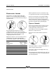
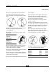
Operator’s Manual Third Edition • First Printing SAFETY RULES Allow for platform movement, electrical line sway or sag and movement due to strong or gusty winds. Electrocution Hazards This machine, even with an optional fiberglass platform, is not electrically insulated and will not provide protection from contact with or proximity to electrical current. Do not use the machine as a ground for welding.
Third Edition • First Printing Operator’s Manual SAFETY RULES Do not raise the platform unless the machine is level. Do not set the machine up on a surface where it cannot be leveled using only the leveling jacks. of the machine. When moving the machine with a forklift or other transport vehicle, the platform should be fully lowered, the machine should be turned off and no personnel shall remain in the platform. Do not use the machine on a moving or mobile surface or vehicle.
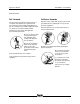
Operator’s Manual Third Edition • First Printing SAFETY RULES Fall Hazards Collision Hazards The guard rail system provides fall protection. If occupants of the platform are required to wear personal fall protection equipment (PFPE) due to job site or employer rules, PFPE equipment and its use shall be in accordance with the PFPE manufacturer’s instructions and applicable governmental requirements.
Third Edition • First Printing Operator’s Manual SAFETY RULES Improper Use Hazard Damaged Machine Hazards Do not leave the machine unattended unless the key is removed to secure from unauthorized use. Do not use a damaged or malfunctioning machine. Bodily Injury Hazard Do not operate the machine with a hydraulic oil or air leak. An air leak or hydraulic leak can penetrate and/or burn skin.
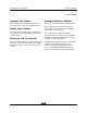
Operator’s Manual Third Edition • First Printing SAFETY RULES Battery and Charger Safety - DC Models Electrocution Hazards Connect the charger to a grounded AC circuit only. Burn Hazards Do not expose the battery or charger to water or rain. Batteries contain acid. Always wear protective clothing and eye wear when working with batteries. Before each use, inspect for damage. Replace damaged components before operating. Lifting Hazard Avoid spilling or contacting battery acid.
Third Edition • First Printing Operator’s Manual SAFETY RULES Decal Legend Genie product decals use symbols, color coding and signal words to identify the following: Safety alert symbol—used to alert personnel to potential personal injury hazards. Obey all safety messages that follow this symbol to avoid possible injury or death. Red—used to indicate the presence of an imminently hazardous situation which, if not avoided, will result in death or serious injury.
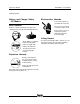
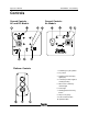
Operator’s Manual Third Edition • First Printing Controls Ground Controls AC and DC Models Ground Controls Air Models Platform Controls 1 Red Emergency Stop button 2 Key switch 3 Outrigger interlock display lights (four) 4 Low battery indicator light for auxiliary lowering 5 DC models: Low battery indicator light 6 Power light 7 Auxiliary platform lowering button 8 Air pressure gauge 9 Control activate button 10 Up/Down switch 8 Genie AWP Super Series Part No.
Third Edition • First Printing Operator’s Manual Legend 1 Lifting eye 2 AC models: Circuit breaker 3 Outrigger storage socket 4 Tilt-back frame retaining pin in strut socket 5 Tilt-back strut 6 Swivel lock 7 Tilt-back frame 8 Loading stop bracket Part No.
Operator’s Manual Third Edition • First Printing Pre-operation Inspection Fundamentals It is the responsibility of the operator to perform a pre-operation inspection and routine maintenance. The pre-operation inspection is a visual inspection performed by the operator prior to each work shift. The inspection is designed to discover if anything is apparently wrong with a machine before the operator performs the function tests.
Third Edition • First Printing Operator’s Manual PRE-OPERATION INSPECTION Pre-operation Inspection o Be sure that the operator’s, safety and responsibilities manuals are complete, legible and in the storage container located on the platform. o Sequencing cables and pulleys o Be sure that all decals are legible and in place. See Decals section. o Mast columns and counterweight o Check for battery fluid leaks and proper fluid level. Add distilled water if needed. See Maintenance section.
Operator’s Manual Third Edition • First Printing Maintenance Check the Battery - DC Models Proper battery condition is essential to good machine performance and safe operation. Improper fluid levels or damaged cables and connections can result in component damage and hazardous conditions. Observe and Obey: Electrocution hazard. Contact with hot or live circuits could result in death or serious injury. Remove all rings, watches and other jewelry.
Third Edition • First Printing Operator’s Manual MAINTENANCE Check the Hydraulic Oil Level Maintaining the hydraulic oil at the proper level is essential to machine operation. Improper hydraulic oil levels can damage hydraulic components. Daily checks allow the inspector to identify changes in oil level that might indicate the presence of hydraulic system problems. 1 Be sure the platform is fully lowered. 2 Check the sight gauge on the side of the hydraulic reservoir.
Operator’s Manual Third Edition • First Printing MAINTENANCE Check the Oil Lubricator Canister Drip Rate - Air Models Maintaining the proper oil drip rate into the lubricator canister is essential to safe operation and good machine performance. Failure to maintain the proper drip rate could result in machine component damage.
Third Edition • First Printing Operator’s Manual Function Tests Fundamentals The function tests are designed to discover any malfunctions before the machine is put into service. The operator must follow the step-by-step instructions to test all machine functions. Do Not Operate Unless: You learn and practice the principles of safe machine operation contained in this operator’s manual. 1 Avoid hazardous situations. 2 Always perform a pre-operation inspection. A malfunctioning machine must never be used.
Operator’s Manual Third Edition • First Printing FUNCTION TESTS Function Tests 8 Repeat this procedure for each of the remaining outriggers. Setup 9 Use the bubble level and adjust the leveling jacks until the machine base is level. 1 Position the machine on a firm surface directly below the desired work area. 2 Connect to the appropriate power source: DC models: Connect the battery pack. AC models: Connect to a grounded 15A AC power supply. Use a 12 gauge / 3.
Third Edition • First Printing Operator’s Manual FUNCTION TESTS 12 Push in the red Emergency Stop button at the platform controls to the off position. 13 Pull out the red Emergency Stop button at the ground controls to the on position. 14 Push in the control activate button and rotate the up/down switch in the direction of intended travel. Result: The up/down function should not operate. Test Outrigger Interlock 23 Connect the power source to the machine. 24 Turn the key switch to platform control.
Operator’s Manual Third Edition • First Printing Workplace Inspection Workplace Inspection Be aware of and avoid the following hazardous situations: Do Not Operate Unless: You learn and practice the principles of safe machine operation contained in this operator’s manual.
Third Edition • First Printing Operator’s Manual Operating Instructions Setup 1 Position the machine on a firm surface directly below the desired work area. You learn and practice the principles of safe machine operation contained in this operator’s manual. 2 Connect to the appropriate power source: DC models: Connect the battery pack. AC models: Connect to a grounded 15A AC power supply. Use a 12 gauge / 3.3mm2 3-wire grounded extension cord no longer than 50 feet / 13 m.
Operator’s Manual Third Edition • First Printing OPERATING INSTRUCTIONS Emergency Stop Push in the red Emergency Stop button at the platform controls or at the ground controls to stop the up function. Platform Raise and Lower 1 Pull out the red Emergency Stop button to the on position at the ground controls. Twist to release the red Emergency Stop button at the platform controls. 2 Push in the control activate button and rotate the up/down switch in the desired direction of travel.
Third Edition • First Printing Operator’s Manual Battery Charging Instructions To Charge Battery 1 Open the battery pack lid to access the battery. 2 Remove the battery vent caps and check the battery acid level. If necessary, add only enough distilled water to cover the plates. Do not overfill prior to the charge cycle. Battery and Charger Instructions 3 Replace the battery vent caps. 4 Be sure that the DC output cord is properly connected to the battery. Black to negative, red to positive.
Operator’s Manual Third Edition • First Printing Transport Instructions Lifting Instructions The number of people required to load and unload a machine is dependent on a number of factors, including but not limited to: · the physical condition, strength and disabilities or prior injuries of the people involved Transport Instructions Observe and Obey: Be sure the transport vehicle capacity and loading surfaces are sufficient to support the machine weight. See the serial label for the machine weight.
Third Edition • First Printing Operator’s Manual TRANSPORT INSTRUCTIONS Loading for Transport 1 Fully lower the platform. 2 Push in the red Emergency Stop buttons, turn the key switch to the off position and remove the key. 3 Remove the outriggers from the base and place them in the storage sockets. 8 Position the machine flush against the loading surface. Lower and lock the stop bracket to the lowest lock pin position above the loading surface.
Operator’s Manual Third Edition • First Printing TRANSPORT INSTRUCTIONS Securing the Machine Use chains or straps of ample load capacity. Winching the Machine onto a Flatbed Truck Use a minimum of 2 chains. 1 Fully lower the platform. Adjust the rigging to prevent damage to the chains. 2 Push in the red Emergency Stop buttons, turn the key switch to the off position and remove the key. 3 Remove the outriggers from the base and place them in the storage sockets.
Third Edition • First Printing Operator’s Manual Tilt-back Operation Instructions Lifting Instructions The number of people required to load and unload a machine is dependent on a number of factors, including but not limited to: Tilt-back Operation Instructions Observe and obey: The retaining pin must be inserted to prevent the spring-loaded tilt-back frame from dropping. Do not tilt the machine back unless the area is clear of personnel and obstructions.
Operator’s Manual Third Edition • First Printing TILTBACK OPERATION INSTRUCTIONS Lowering the Tilt-back Assembly Tilting Back the Machine 1 Be sure the area behind the machine and under the tilt-back frame is clear of personnel and obstructions. 2 Fully lower the platform. 3 Remove the outriggers from the base and place them in the storage sockets. The tilt-back frame is spring loaded and will immediately fall outward when the retaining pin is removed.
Third Edition • First Printing Operator’s Manual TILTBACK OPERATION INSTRUCTIONS Returning the Machine to Standing Position Stowing the Tilt-back Assembly 1 Remove the retaining pin. 1 Be sure the area below the machine base and T-handle is clear of personnel and obstructions. 2 Slide out the T-handle untl the lock pin snaps into place. 3 Carefully pull down the T-handle until the machine rests at midtilt position.
Operator’s Manual Third Edition • First Printing Decals Inspection for Decals with Words Determine whether the decals on your machine have words or symbols. Use the appropriate inspection to verify that all decals are legible and in place. Part No. Description Quantity Part No.
Third Edition • First Printing Operator’s Manual DECALS Note: Platform decals may be in diffferent locations on optional fiberglass basket. Models with Tilt-back Frame Part No.
Operator’s Manual Third Edition • First Printing DECALS Inspection for Decals with Symbols Determine whether the decals on your machine have words or symbols. Use the appropriate inspection to verify that all decals are legible and in place. Part No. Description Quantity Part No.
Third Edition • First Printing Operator’s Manual DECALS Note: Platform decals may be in diffferent locations on optional fiberglass basket. Models with Tilt-back Frame Part No.
Operator’s Manual Third Edition • First Printing Specifications Machine Specifications Height, working maximum AWP-20S AWP-25S AWP-30S AWP-36S AWP-40S 26 ft 1 in / 8.0 m 30 ft 9 in / 9.4 m 35 ft 6 in / 10.8 m 42 ft 5 in / 12.9 m 46 ft 3 in / 4.1 m Height, platform maximum AWP-20S AWP-25S AWP-30S AWP-36S AWP-40S 20 ft 1 in / 6.1 m 24 ft 9 in / 7.6 m 29 ft 6 in / 9.0 m 36 ft 6 in / 11.1 m 40 ft 3 in / 12.3 m Height, stowed AWP-20S, 25S, 30S AWP-36S, 40S 78 in / 2.0 m 1091/2 in / 2.
Third Edition • First Printing Operator’s Manual SPECIFICATIONS Outrigger Specifications Standard Base AWP-36S AWP-40S Outrigger footprint (l x w) ANSI / CSA 831/4 x 751/4 in 2.1 x 1.9 m 89 x 81 in 2.3 x 2.0 m Outrigger footprint (l x w) CE / AUS Indoor 831/4 x 751/4 in 2.1 x 1.9 m 89 x 81 in 2.3 x 2.0 m 139 x 131 in 3.5 x 3.3 m 153 x 145 in 3.9 x 3.7 m Corner access/wall access* ANSI / CSA 281/2 / 141/4 in 72.7 / 36.2 cm 311/4 / 141/2 in 79.4 / 37.
Genie North America Phone 425.881.1800 Toll Free USA and Canada 800.536.1800 Fax 425.883.3475 Genie Australia Pty Ltd. Phone +61 7 3375 1660 Fax +61 7 3375 1002 Genie Scandinavia Phone +46 31 575100 Fax +46 31 579020 Genie France Phone +33 (0)2 37 26 09 99 Fax +33 (0)2 37 26 09 98 Genie Iberica Phone +34 93 579 5042 Fax +34 93 579 5059 Genie Germany Phone +49 (0)4202 88520 Fax +49 (0)4202 8852-20 Genie U.K.