Model 1022/1024 Includes Remote Control (Up to 7 Single Button Programmable Controls Available) Safety Beam System must be installed to close door. For use only with sectional doors. Your Residential Operator comes with a Rail Assembly which is standard for up to a 7 foot high door. Homelink® and Car2U™ compatible For Answers and Assistance: 1.800.354.3643 or visit www.geniecompany.com SAVE THIS MANUAL FOR FUTURE REFERENCE Homelink® is a registered trademark of Johnson Controls Technology Company.
SAFETY INFORMATION OVERVIEW OF POTENTIAL HAZARDS Garage doors are large, heavy objects that move with the help of springs under high tension and electric motors. Since moving objects, springs under tension, and electric motors can cause injuries, your safety and the safety of others depend on the owner or user of this system to read, understand and implement the information in this manual.
TABLE OF CONTENTS OPERATOR FEATURES SECTION . . . . . . . . . . . . . . . . . . . . . . . . . . . . . . . . . . . . . . . . . PAGE SAFETY INFORMATION . . . . . . . . . . . . . . . . . . . . . . . . . . . . . . . . . 2 OPERATOR FEATURES . . . . . . . . . . . . . . . . . . . . . . . . . . . . . . . . . 3 SAFETY FEATURES . . . . . . . . . . . . . . . . . . . . . . . . . . . . . . . . . . . . 3 PRE-INSTALLATION CHECK LIST . . . . . . . . . . . . . . . . . . . . . . . 4-5 RECOMMENDED TOOLS . . . . . . . . . .
PRE-INSTALLATION CHECK LIST FOR HELP-1.800.354.3643 OR WWW.GENIECOMPANY.COM Things to consider if you are planning to "Do-it-yourself." This operator is designed for use with SECTIONAL doors only. In many cases you will be replacing an existing door operator with a new one, however, if this will be the first operator installed there are some pre-installation issues which need to be addressed.
TYPICAL SECTIONAL DOOR INSTALLATION 5 1 Pg. 18 FOR HELP-1.800.354.3643 OR WWW.GENIECOMPANY.COM Pg. 12 2 TYPICAL SUPPORT BRACKET Pg. 11-12 ADDED HEADER BRACKET MOUNTING BOARD BRACES POWER CORD (APPROX. 45 IN.) TO 120V GROUNDED OUTLET EXTENSION SPRING OR TORSION SPRING 4 NOTE: This operator is designed for use with SECTIONAL doors only. Pg. 13 Pg. 16-17 Pg. 16-17 6 3 3 Pg. 10 SAFETY BEAMS MAX. 6" MIN. 5" 7 Pg.
RECOMMENDED TOOLS FOR HELP-1.800.354.3643 OR WWW.GENIECOMPANY.COM Pencil 3/16" Drill Bit Carpenter’s level Drill Wire strippers Adjustable wrench Ratchet Tape measure Step ladder Safety Glasses 1/4", 7/16", 3/8" and 1/2" Sockets Phillips screwdrivers Hammer PARTS IDENTIFICATION - Not Shown Full Size . ARRANGING BOX CONTENTS FOR ASSEMBLY ORGANISATION DU CONTENU DE LA BOÎTE POUR LE MONTAGE DISPOSICIÓN DEL CONTENIDO DE LA BOLSA PARA EL MONTAJE Remove internal boxes. Enlever les boîtes internes.
FASTENERS - Shown Full size (See Parts List below for full description.) BAG NO.
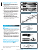
1-PIECE RAIL HARDWARE ASSEMBLED VIEW FOR HELP-1.800.354.3643 OR WWW.GENIECOMPANY.COM Power Cord Rail with chain Power Head Trolley Slide Nh at SIO Nor De ined a tra ons G TE jury by cti RINus Inbe maded instru Release Knob TE ed NOors nect do nta or me Co r So cing. utofor er bra distrib tur s.
IMPORTANT INSTALLATION INSTRUCTIONS WARNING: To reduce the risk of severe injury or death: 1. READ AND FOLLOW ALL SAFETY, INSTALLATION AND OPERATION INSTRUCTIONS. (If you have questions or do not understand an instruction, call The Genie Company or an authorized Genie Dealer.) 2. Install only on a properly balanced sectional garage door. An improperly balanced door could cause severe injury.
NOTE: For split rail clamps, nuts, and bolts locate Bag 0 from Box 1. 3. Remove the two rail sections that are not connected to the chain and place them on floor (Fig. 1-2, A). 4. Carefully remove the third rail section with chain and plastic sleeve. Place rail section on floor and extend chain straight out. (Fig. 1-2, B). Chain and rail should extend approximately 7 feet. 5. Remove wire ties and plastic bag from chain. Leave chain extended straight out on floor.
2 INSTALLATION FOR HELP-1.800.354.3643 OR WWW.GENIECOMPANY.COM b) - extend vertical line HEADER AND DOOR MOUNTING BRACKETS: 2-1/2" CAUTION Header bracket must be fastened to garage framing. Do NOT fasten to drywall, particle board, plaster or other such materials. 1. Finding header bracket mounting location. • Close garage door. – Use a pencil and level. a) Mark center of garage door (one-half overall width) on the wall with 6" vertical line at top edge of door.
MOUNTING THE OPERATOR: HEADER BRACKET 1. Getting started. • Position assembled rail on wall next to header bracket. (Fig. 2-4). – Place material on floor under power head to protect from scratching. (A box, stool, or similar device may be needed to clear a torsion spring.) VIEW FROM ABOVE (not to scale) NOTE: For header bracket pins locate Bag 2 from Box 1. 2. Mounting the assembly. • Attach rail to header bracket using clevis pin and cotter pin.
DOOR BRACKET: CAUTION Doors made of masonite, lightweight wood, fiberglass, and sheet metal must be properly braced before mounting door operator. Contact door manufacturer or distributor for a bracing kit. The Genie Company is not responsible for damage caused due to improperly braced door. NOTE: For door bracket and bolts locate Bag 4 from Box 2. 1. Finding door bracket mounting location.
3 WALL CONTROL INSTALLATION FOR HELP-1.800.354.3643 OR WWW.GENIECOMPANY.COM Wire from power head to wall control. WARNING Verify there is NO power to the operator before installing wall control wires and wall control. CAUTION Staples which are too tight can cut or pinch wires. Cut or pinched wires can cause the wall control to stop working. When using the insulated staples, make sure you fasten them only as tightly as needed to hold the wire snugly.
3.Securely fasten wires. • Securely fasten wires to ceiling and wall using insulated staples provided. – Use insulated staples. Insulated – Staples should be snug only. Staple • If rear cover is attached to power head, remove it. • On power head: – Route wall control wires through wire guide. – Split and strip ends of wire (Fig. 3-2 on previous page). – Insert wire into terminal holes and lightly press in the orange locking clips above each terminal hole.
4 SAFETY BEAM SYSTEM INSTALLATION FOR HELP-1.800.354.3643 OR WWW.GENIECOMPANY.COM WARNING There should be no electrical power to the operator while installing Safety Beam wires. If you have plugged in the power cord—UNPLUG IT NOW! NOTE: The operator will not close the door automatically unless the Safety Beam System is installed. NOTE: For Sensors, screws, wire, and insulated staples locate items and Bag 8 from Box 3. 1. Mounting brackets.
3b. Wiring (pre-wired). • Route wire from wall to Safety Beam sensors. (Fig. 4-5b). • Splice pre-wiring to shortened sensor wire, match wire pairs dash-to-dash and plain-to-plain. - Trim sensor wire to approximately one foot (1 ft) from sensor. - Split and strip ends of sensor wires and pre-wired wires. (Fig. 4-7) - Splice wires together with (provided) wire nuts. • Route wire from ceiling to power head. Wire Nut (Fig. 4-5b). • Securely fasten wires where they exit wall and ceiling as you go.
5 CONNECTING TO POWER FOR HELP-1.800.354.3643 OR WWW.GENIECOMPANY.COM WARNING • To reduce the risk of electrical shock, this equipment has a grounded type plug that includes a third (grounding) pin. This plug will only fit a grounded type outlet. If you do not have a grounded outlet, contact a qualified licensed electrician to install one. DO NOT alter the plug in any way. The door operator must be properly grounded in order to prevent personal injury and damage to the components.
6 DOOR LIMITS FOR HELP-1.800.354.3643 OR WWW.GENIECOMPANY.COM WARNING • Severe injury or death can result if the door closing force is set too high. • Never increase the door closing force above the minimum required to move the door. • Never adjust force to compensate for a sticking or binding door. • Once per month perform CONTACT REVERSE TEST as described on the next page and in Section 10. Limit Controls location on power head.
CARRIAGE LOCK DOOR The Carriage Lock can be manually engaged or disengaged. • To disengage Carriage Lock – Pull handle towards opener. • To engage Carriage Lock – Pull handle towards door. UP/DOWN FORCE 1. By turning the Down Force Control clockwise, the DOWN force can be increased. By turning the Down Force Control counter-clockwise, the DOWN force can be decreased. Set the DOWN force level at the minimum force required to close door without reversing. 2.
7 PROGRAMMING REMOTE CONTROLS WARNING A moving door can cause serious injury or death. 1. Keep people clear of opening while door is moving. 2. Do NOT allow children to play with Wireless Keypad. 3. During programming, the door opener could begin to run, so stay away from the moving door and its parts. To keep the door from moving, close the door and disconnect it from the Opener by pulling the Emergency Release. NOTE: For remote control locate Box 3. 1a. Single Button Remote Programming.
8 REMOTE CONTROL BATTERY REPLACEMENT AND VISOR CLIP INSTALLATION 1. Battery replacement. • Use coin, ball-point pen or similar device. – Gently push straight in on battery cover lock tab as shown (Fig. 8-1). • Flip open battery cover. – Remove old battery. • Make sure new battery is facing proper direction (Match battery polarity with symbols inside battery cover) (Fig. 8-2). – Recommended replacement battery type: Alkaline A23, 12 volt. • Slip new battery into place. – Snap battery cover shut.
IMPORTANT SAFETY INSTRUCTIONS WARNING: To reduce the risk of severe injury or death: 1. READ AND FOLLOW ALL INSTRUCTIONS. 2. Never let children operate or play with the door controls. Keep the remote control away from children. 3. Always keep the moving door in sight and away from people and objects until the door is completely closed. NO ONE SHOULD CROSS THE PATH OF THE MOVING DOOR. 4. NEVER GO UNDER A STOPPED, PARTIALLY OPEN DOOR. 5. Test operator monthly.
CIRCUIT WIRING DIAGRAM FOR HELP-1.800.354.3643 OR WWW.GENIECOMPANY.COM Operator circuit wiring diagram. This wiring diagram is for reference only. Opening Cover May Cause Electric Shock. Remove power from operator prior to removing cover.
TROUBLESHOOTING GUIDE - OPERATION PROBLEM FOR HELP-1.800.354.3643 OR WWW.GENIECOMPANY.COM WHAT TO DO Operator does NOT run from wall control. • Check power source. – Plug a lamp into outlet used for power head. If lamp works, power source is OK. – If not, check fuse or circuit breaker. • If power is OK. – Check connections at power head terminals. – Check connections at wall control. • Check for broken or cut wires. Staples can cut insulation and short wires. Repair or replace.
TROUBLESHOOTING GUIDE - POWER HEAD LED Power head LED Red LED Green LED showing showing OFF OFF FOR HELP-1.800.354.3643 OR WWW.GENIECOMPANY.
TRANSMITTER COMPLIANCE STATEMENT Transmitters comply with all United States and Canadian legal requirements as of the date of manufacture. No warranty is made that they comply with all legal requirements of any other jurisdiction. If transmitters are to be used in another country, the importer must determine compliance with any local laws and regulations which may differ from United States and Canadian requirements prior to use.
The Genie Company Professional Access Systems LIMITED WARRANTY What is covered: Any defect in material and product workmanship from personal, normal household use in accordance with the Owner’s Manual. How to get warranty service: To obtain warranty service for your Genie product, you must provide proof of the date and place of purchase of the product. For how long: Limited 1 year warranty on parts, 5 years on motor. 1. Do-It-Yourself-Service. Call the Genie Consumer Connection toll free at 1.800.354.