Operator’s Manual with Maintenance Information First Edition Seventh Printing Part No.
Operator's Manual First Edition · Seventh Printing Important Read, understand and obey these safety rules and operating instructions before operating this machine. Only trained and authorized personnel shall be permitted to operate this machine. This manual should be considered a permanent part of your machine and should remain with the machine at all times. If you have any questions, call Genie Industries. Contents Page Safety ........................................................................
First Edition · Seventh Printing Operator's Manual Safety Rules Danger Failure to obey the instructions and safety rules in this manual will result in death or serious injury. Do Not Operate Unless: You learn and practice the principles of safe machine operation contained in this operator's manual. 1 Avoid hazardous situations. Know and understand the safety rules before going on to the next section. 2 Always perform a pre-operation inspection. 3 Always perform function tests prior to use.
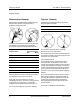
Operator's Manual First Edition · Seventh Printing SAFETY RULES Electrocution Hazards Tip-over Hazards This machine is not electrically insulated and will not provide protection from contact with or proximity to electrical current. Occupants and equipment shall not exceed the maximum platform capacity.
First Edition · Seventh Printing Operator's Manual SAFETY RULES Do not operate the machine in strong or gusty winds. Do not increase the surface area of the platform or the load. Increasing the area exposed to the wind will decrease machine stability. Do not modify or alter an aerial work platform. Mounting attachments for holding tools or other materials onto the platform, toeboards or guard rail system can increase the weight in the platform and the surface area of the platform or the load.
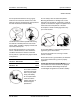
Operator's Manual First Edition · Seventh Printing SAFETY RULES Do not use the machine as a crane. Bodily Injury Hazard Do not push the machine or other objects with the boom. Do not contact adjacent structures with the boom. Do not operate the machine with a hydraulic oil or air leak. An air leak or hydraulic leak can penetrate and/or burn skin. Do not tie the boom or platform to adjacent structures. Always operate the machine in a well-ventilated area to avoid carbon monoxide poisoning.
First Edition · Seventh Printing Operator's Manual SAFETY RULES Do not lower the boom unless the area below is clear of personnel and obstructions. Damaged Machine Hazards Do not use a damaged or malfunctioning machine. Conduct a thorough pre-operation inspection of the machine and test all functions before each work shift. Immediately tag and remove from service a damaged or malfunctioning machine.
Operator's Manual First Edition · Seventh Printing SAFETY RULES Decal Legend Genie product decals use symbols, color coding and signal words to identify the following: Safety alert symbol—used to alert personnel to potential personal injury hazards. Obey all safety messages that follow this symbol to avoid possible injury or death. Red—used to indicate the presence of an imminently hazardous situation which, if not avoided, will result in death or serious injury.
First Edition · Seventh Printing Operator's Manual Controls 6 7 8 9 10 5 4 11 3 2 12 1 13 19 18 17 16 15 14 Ground Control Panel 1 Platform rotate switch 11 Diesel models: Water temperature light 2 Turntable rotate switch 12 Gasoline/LPG models: Choke switch Diesel models: Glow plug switch (option) 3 Primary boom up/down switch 4 Primary boom extend/retract switch 5 Gasoline/LPG models: Fuel select switch 13 Function enable switch 14 Engine start switch 15 15A breaker for engine electr
Operator's Manual First Edition · Seventh Printing CONTROLS 1 2 3 4 13 18 5 17 16 Platform Control Panel 6 Drive speed select switch 1 Horn button 7 Glow plug switch 2 Platform level switch 8 Engine start switch 3 Platform rotate switch 9 Engine idle (rpm) select switch 4 Z-45/25J models only: Jib boom up/down switch 10 Gasoline/LPG models: Gasoline/LPG select switch 5 Auxiliary power switch 8 Genie Z-45/25 & Genie Z-45/25J Part No.
First Edition · Seventh Printing Operator's Manual CONTROLS 7 15 8 14 9 13 10 13 11 12 11 Red Emergency Stop button 15 Drive enable switch 12 Dual axis proportional control handle for drive and steer functions OR Proportional control handle for drive function and thumb rocker for steer function 16 Proportional control handle for secondary boom up/down function 13 used for optional equipment 14 Drive enable indicator light Part No.
Operator's Manual First Edition · Seventh Printing Pre-operation Inspection Fundamentals It is the responsibility of the operator to perform a Pre-operation Inspection and routine maintenance. Do Not Operate Unless: You learn and practice the principles of safe machine operation contained in this operator's manual. 1 Avoid hazardous situations. 2 Always perform a pre-operation inspection. Know and understand the pre-operation inspection before going on to the next section.
First Edition · Seventh Printing Operator's Manual PRE-OPERATION INSPECTION Pre-operation Inspection o Be sure that the operator’s, safety and responsibilities manuals are complete, legible and in the storage container located in the platform. o Be sure that all decals are legible and in place. See Decals section. o Check for engine oil leaks and proper oil level. Add oil if needed. See Maintenance section. o Check for hydraulic oil leaks and proper oil level. Add oil if needed. See Maintenance section.
Operator's Manual First Edition · Seventh Printing Maintenance Check the Engine Oil Level Maintaining the proper engine oil level is essential to good engine performance and service life. Operating the machine with an improper oil level can damage engine components. Observe and Obey: Only routine maintenance items specified in this manual shall be performed by the operator.
First Edition · Seventh Printing Operator's Manual MAINTENANCE Check the Hydraulic Oil Level Deutz Engine F3L 1011F Oil viscosity requirements below 60°F / 15.5°C (synthetic) 5W-30 -10°F to 90°F / -23°C to 32°C 10W-40 above -4°F / -34°C 15W-40 Engine oil should have properties of API classification CC/SE, CD/SE, SF/CC or SF/CD grades. Units ship with 10-40 CC/SG. Perkins Engine 104-22 Oil viscosity requirements below 60°F / 15.
Operator's Manual First Edition · Seventh Printing MAINTENANCE Check the Engine Coolant Level Ford and Perkins Models Maintaining the engine coolant at the proper level is essential to engine service life. Improper coolant level will affect the engine's cooling capability and damage engine components. Daily checks will allow the inspector to identify changes in coolant level that might indicate cooling system problems.
First Edition · Seventh Printing Operator's Manual MAINTENANCE Check the Tire Pressure Scheduled Maintenance Bodily injury hazard. An overinflated tire can explode, which can result in death or serious injury. Tip-over hazard. Do not use temporary flat tire repair products. Maintenance performed quarterly, annually and every two years must be completed by a person trained and qualified to perform maintenance on this machine according to the procedures found in the service manual for this machine.
Operator's Manual First Edition · Seventh Printing Function Tests Fundamentals The Function Tests are designed to discover any malfunctions before the machine is put into service. The operator must follow the step-by-step instructions to test all machine functions. Do Not Operate Unless: You learn and practice the principles of safe machine operation contained in this operator's manual. 1 Avoid hazardous situations. A malfunctioning machine must never be used.
First Edition · Seventh Printing Operator's Manual FUNCTION TESTS 1 Select a test area that is firm, level and free of obstruction. At the Ground Controls 2 Turn the key switch to ground control. 3 Pull out the red Emergency Stop button to the on position. Result: Beacon (if equipped) should flash. 4 Start the engine. See Operating Instruction section. Test Emergency Stop 5 Push in the red Emergency Stop button to the off position. Result: The engine will shut off after 2 to 3 seconds.
Operator's Manual First Edition · Seventh Printing FUNCTION TESTS At the Platform Controls Test Machine Functions Test Emergency Stop 25 Press down the foot switch. 15 Turn the key switch to platform control and restart the engine. 26 Activate each machine function control handle or toggle switch. 16 Push in the platform red Emergency Stop button to the off position. Result: All boom/platform functions should operate through a full cycle. Result: The engine will shut off after 2 or 3 seconds.
First Edition · Seventh Printing Operator's Manual FUNCTION TESTS Test Drive and Braking Test the Drive Enable System 31 Press down the foot switch. 34 Move the lift/drive select switch to the lift position (if equipped). 32 Slowly move the drive control handle in the direction indicated by the blue arrow on the control panel until the machine begins to move, then return the handle to the center position.
Operator's Manual First Edition · Seventh Printing FUNCTION TESTS Test Limited Drive Speed Z-45/25 & Z-45/25J Standard Base Models ANSI and CSA Z-45/25 & Z-45/25J Narrow Base Models before serial number 19081 40 Move the lift/drive select switch to the lift position (if equipped). 50 Move the lift/drive select switch to the lift position (if equipped). 51 Lower the secondary boom to the stowed position. 52 Extend the primary boom approximately 1 foot / 30 cm. 41 Press down the foot switch.
First Edition · Seventh Printing Operator's Manual FUNCTION TESTS 42 Raise the primary boom approximately 2 feet / 61 cm. 43 Move the lift/drive select switch to the drive position (if equipped). 44 Slowly move the drive control handle to the full drive position. Result: The maximum achievable drive speed with the primary boom raised should not exceed 0.5 foot / 15 cm per second. 45 Move the lift/drive select switch to the lift position (if equipped). 46 Lower the primary boom to the stowed position.
Operator's Manual First Edition · Seventh Printing FUNCTION TESTS Test Auxiliary Controls Test the Lift/Drive Select Function (CE models) 62 Shut the engine off. 63 Pull out the red Emergency Stop button to the on position. 64 Move the lift/drive select switch to the lift position (if equipped). Machines with lift/drive select switch: 67 Move the lift/drive select switch to the lift position. 68 Press down the foot switch. 69 Move the drive control handle off center. 65 Press down the foot switch.
First Edition · Seventh Printing Operator's Manual Workplace Inspection Workplace Inspection Be aware of and avoid the following hazardous situations: Do Not Operate Unless: You learn and practice the principles of safe machine operation contained in this operator's manual.
Operator's Manual First Edition · Seventh Printing Operating Instructions Fundamentals The Operating Instructions section provides instructions for each aspect of machine operation. It is the operator's responsibility to follow all the safety rules and instructions in the operator's, safety and responsibilities manuals. Do Not Operate Unless: You learn and practice the principles of safe machine operation contained in this operator's manual. 1 Avoid hazardous situations.
First Edition · Seventh Printing Operator's Manual OPERATING INSTRUCTIONS Starting the Engine Auxiliary Controls 1 At the ground controls, turn the key switch to the desired position. Use auxiliary power if the primary power source (engine) fails. 2 Be sure both ground and platform control red Emergency Stop buttons are pulled out to the on position. 1 Turn the key switch to ground or platform control. 3 Gasoline/LPG models: Choose fuel by moving the fuel select switch to the desired position.
Operator's Manual First Edition · Seventh Printing OPERATING INSTRUCTIONS To Position Platform To Steer 1 Hold the function enable switch to either side. 1 Move the lift/drive select switch to the drive position (if equipped). 2 Move the appropriate toggle switch according to the markings on the control panel. Drive and steer functions are not available from the ground controls.
First Edition · Seventh Printing Operator's Manual OPERATING INSTRUCTIONS Drive Enable Engine Idle Select (rpm) Light on indicates that the boom has moved just past either non-steer wheel and the drive function has been interrupted. Select the engine idle speed (rpm) using the symbols on the control panel. To drive, hold the drive enable switch to either side and slowly move the drive control handle off center.
Operator's Manual First Edition · Seventh Printing OPERATING INSTRUCTIONS Check Engine Light (if equipped) Light on and engine stopped: Tag the machine and remove from service. Light on and engine still running: Contact service personnel within 24 hours. Stopping the Engine Push in the red Emergency Stop button and turn the key switch to the off position. After Each Use 1 Select a safe parking location—firm level surface, clear of obstruction and traffic.
First Edition · Seventh Printing Operator's Manual Transport Free-wheel Configuration for Winching Chock the wheels to prevent the machine from rolling. Release the non-steer wheel brakes by turning over the drive hub disconnect caps (see below). Transport Instructions Observe and Obey: The transport vehicle must be parked on a level surface. The transport vehicle must be secured to prevent rolling while the machine is being loaded.
Operator's Manual First Edition · Seventh Printing Decals Decal Inspection Use the pictures on this and the next page to verify that all decals are legible and in place. Below is a numerical list with quantities and descriptions. Part No. Decal Description Part No.
First Edition · Seventh Printing Operator's Manual DECALS Ground Controls Side Platform Drive Chassis Engine Side Shading indicates decal is hidden from view, i.e. under covers Part No.
Operator's Manual First Edition · Seventh Printing Specifications Standard Base Models Z-45/25 (no jib) Z-45/25J (jib) Standard Base Models Height, working maximum 51 ft 8 in 15.74 m 51 ft 6 in 15.69 m Controls Height, platform maximum 45 ft 8 in 13.9 m 45 ft 6 in 13.8 m Height, stowed maximum 6 ft 10 in 2.1 m 6 ft 10 in 2.1 m Horizontal reach maximum 124 ft 6 in 17.5 m 25 ft 3 in 7.7 m 7 ft 4 in 2.2 m 7 ft 4 in 2.2 m 18 ft 5.5 m 22 ft 3 in 6.
First Edition · Seventh Printing Operator's Manual SPECIFICATIONS Narrow Base Models Z-45/25 (no jib) Z-45/25J (jib) Narrow Base Models Height, working maximum 51 ft 5 in 15.7 m 51 ft 3 in 15.6 m Controls Height, platform maximum 45 ft 5 in 13.9 m 45 ft 3 in 13.8 m Height, stowed maximum 6 ft 7 in 2.05 m 6 ft 7 in 2.05 m Horizontal reach maximum 124 ft 6 in 17.5 m 25 ft 3 in 7.7 m 5 ft 9 in 1.8 m 5 ft 9 in 1.8 m 18 ft 5.5 m 22 ft 3 in 6.
California Proposition 65 WARNING The exhaust from this product contains chemicals known to the State of California to cause cancer, birth defects or other reproductive harm. Phone 425.881.1800 Toll Free USA and Canada 800.536.1800 Fax 425.883.