Safety Isolating Transformer Models: ISO XFR-75W ISO XFR-100W SERVICE MANUAL Monitor Models: 1493 1793 1993 2093 2793 3693
YEAR LIMITED WARRANTY This product is warranted by CERONIX to be free of defects in material and workmanship for a period of two years from the date of purchase. All parts and labor are free of charge during the warranty period. This warranty does not cover mechanical breakage due to physical abuse. It is the customer's responsibility for shipping the defective unit to and from CERONIX or one of the authorized service centers for repair. Please attach a note describing the problem. CERONIX Inc.
ABOUT THIS MANUAL This manual is specifically written to aid the service technician, repairing CERONIX Models 1493, 1793, 1993, 2093, 2793, and 3693 color monitors. There are three main sections: 1. General Description. 2. Circuit Description. 3. Repair Setup and Appendix.
TABLE OF CONTENTS About This Manual............................................................................................................. i Table of Contents................................................................................................................ii-iii CERONIX Monitor Simplified Block Diagram................................................................. 1 Installation Instructions; English, French, and German................................................
TABLE OF CONTENTS Video Amplifier Circuit, Function, Description.................................................................68 Video Amplifier Circuit Description and Schematic......................................................... 68-69 Video Board Power Supply and Arc Protect Schematic.................................................... 70 CRT Auto Bias and Auto Bright Circuit, Function, Description......................................
Monitor Simplified Block Diagram. VIDEO Output VIDEO Interface Drive Electronics Blanking SYNC Output VIDEO Amps. CRT AUTO BIAS Vertical Deflection FBT IB Horizontal Deflection Remote Controls Isolated Power Horizontal Size Control Fault & High Temp. Detection POWER SUPPLY This block diagram gives a broad view of the circuit organization of the 1493, 1793, 1993, 2093, 2793, and 3693 monitors.
Installation Instructions For The XX93 Monitors. 1. A 3 amp slow blow fuse (for the degaussing current) and a 75 VA isolation transformer are the minimum requirements for using our monitor in a product. 2. Unpack the monitor. 3. Install the monitor in the enclosure. Refer to the installation instructions supplied by the system manufacturer for details of mounting the monitor in the enclosure. 4. Connect the green/yellow ground wire to the earth ground connection on the enclosure.
Instructions d´installation des écrans XX93. 1. Un fusible á fusion lente de 3 amp (pour le courant du champ magnétique d´adjustement) et un transformateur d´isolation de 75 VA sont le minimum requis pour utiliser nos écrans dans un produit. 2. Déballer l´écran. 3. Installer l´écran dans son carter. Se référer aux instructions d´installation foumies par le fabriquant du systéme pour les détails de montage de l´écran dans le carter. 4. Relier le fil de terre vert/jaune á la prise de terre sur le carter.
Installationsanweisungen für die XX93 Monitore. 1. Ein 3 Ampère-T sicherung (für die degaussing-Strömung) und ein 75 VA Isoliertransformator ist die Minimum-Forderung für benutzen unseren Monitoren in einem Produkt. 2. Packen Sie den Monitor aus. 3. Schließen Sie den Monitor im Gehause an. Für Details, Folgen Sie den Installation-Anweisungen, Vom Lieferanten der Antriebelektronik. 4. Verbinden Sie den Grüne/Gelben Schutzleiter zum Erdung anschluß auf dem Gehause.
CERONIX XX93 Monitor Electrical Specification. INPUTS 1. Standard Video Configurations, available, are: Min. Typ. Max .75V Black level Video Saturated color 0.00V 0.75V 0.02V 0.77V 0.04V 0.79V Black level Saturated color 0.00V 1.00V 0.02V 1.02V 0.04V 1.04V .75V Black level Video Saturated color Blk-.02V Blank Blk+.02V A. Positive Analog, DC Coupled. Video Source D-A .6mA To Amp. Video 75Ω 75Ω Gnd Monitor B. Positive Analog, AC Coupled.
CERONIX XX93 Monitor Electrical Specification. 2. The Sync signals may be of either polarity and separate or composite. Hs 1.8K Model Min. Sync Source .15V High input voltage 2.2V Vs 1.8K Low input voltage -2.7V 220 Ω, 2 PL Gnd Monitor Horizontal sync pulse 1.5uS For composite sync, vertical and horizontal Vertical sync pulse 65uS sync lines are connected together. Horizontal frequencies: 15.5KHz Custom horizontal frequencies from 15KHz to 39KHz are available upon request. Typ. Max 3.5V .30V 4.
CERONIX XX93 Monitor Electrical Specification. 4. Five Controls are located on a separate PCB for easy access. H SIZE--------------Horizontal raster size V SIZE---------------Vertical raster size V RAS. POS.-----Vertical raster position H POS-------Horizontal picture position M GAIN---------------------Master gain Model 1493 Min. Max. Model 1793 Min. Max. Model 1993 Min. Max. 10.1" 11.1" 7.3" 8.3" .50" 0" 11.9" 12.9" 8.6" 9.6" .50" 0" 13.4" 14.4" 9.8" 10.8" .
CERONIX 7. Picture tube Useful diagonal XX93 Monitor Electrical Specification. 1493-CGA/VGA/SVGA Inch 13.2 11.1 8.3 mm 335 281 211 1793-VGA/SVGA Inch 16 12.9 9.7 mm 407 328 246 1793-SVGA Inch 16.1 12.9 9.6 mm 409 328 245 1993-VGA/SVGA Inch 18 14.4 10.8 mm 457 366 274 Useful horizontal Useful vertical Useful area 92.1 in2 593 cm2 125 in2 807 cm 2 124 in2 804 cm 2 Spacing of dot/line trios .0110" .28mm .0106" .27mm .0098" .
Refer to the block diagram on page 15 (foldout) when reading this description. A The Video Interface is designed around a custom IC and will accept DC or AC coupled positive analog video signals. It can also be used with negative analog and 4 line TTL. This IC has a built in multiplier circuit for the master gain control and blanking functions. Resistors are used to protect the IC and to set the gain. The programmed gain is dependent on the input signal amplitude except with the TTL mode.
E The CRT Auto Bias IC is a combination of digital and analog circuitry. The digital part is a counter and control logic which steps the analog circuits through a sequence of sample and hold conditions. The analog part uses a transconductance amplifier to control the voltage on a 10uF capacitor (one per gun). This voltage is buffered and sent to the video amplifiers as the bias voltage. In monitors without CRT auto bias, this voltage is adjusted manually using a setup procedure to set the color balance.
H The CRT for the 1493, 1793 and 2093 monitors have a 90° deflection angle. The 1993 incorporates 100° while the 2793 CRT has 110° and the 3693 has 111° deflection angles. These picture tubes have integral implosion protection and a EHT of 25KV. H1 The Vertical Dynamic Focus amplifies the parabolic waveform across the vertical coupling capacitor from about 3Vp-p to about 200Vp-p, depending on CRT requirements. This waveform sharpens the top and bottom portion of the raster on dual focus CRT's.
The sync pulse from the LA7851 triggers a one shot in the LA7838 which clamps the vertical ramp generation capacitor to 5V during the first half of vertical retrace. The ramp generation capacitor then charges via a constant current set by an external resistor. This resistor is connected to the V SIZE pot, located on the remote control board, for the vertical size adjustment. The vertical drive is a differential amplifier which compares the ramp voltage to the yoke return feedback current.
Q The Remote Control PCB houses the: CONTROL 1. 2. 3. 4. 5. DESCRIPTION CIRCUIT H SIZE ----------- Horizontal raster size --------- Diode modulator V SIZE ----------- Vertical raster size ------------- Vertical control V RAS. POS. --- Vertical raster position ------- DC current to V. yoke H POS ------------ Horizontal picture position -- H. sync delay M GAIN ---------- Master gain ---------------------- Video interface R The Horizontal Size Control circuit has four inputs: # 1. 2. 3. 4.
XX93 Monitor Block Diagram. U The Switching Regulator is synchronized to the horizontal pulse and drives a power MOSFET. Unlike most regulators that have a common GND, this power supply has a common V+ and current is supplied from V- to GND. The MOSFET is connected to V– and signal ground (GND) through a transformer which is used as an inductor for series switch mode regulation.
Product safety note: Components marked by the When replacing any of CRT HEAT SINK 378 211 1.8K 4 4.5-5.3V Vs 5Vpp 16,E5 368 208 248 OPEN HORIZONTAL BLANKING OUT .039uF 078 RC4 RC1 333 0Ω 220uF 1 2.7K 2 1.8K 7.3VDC Hs 5.5Vpp 01,D6 220uF Vs 8 I4 202 17 5 U 412Ω 105Ω 604Ω 260 244 245 362 363 361 076 5 213 064 258 +12V 17 DELAYED SYNC O/S 012 3 7.3-8.7V Hs 4Vpp 02,D6 7.3-8.7V Vs -.2VDC Hs 4Vpp 03,D6 1.5Vpp 04,E6 4 228 6 R IN 2 11 8.
C D E F G H I J NOTES 7812, 296 305 0Ω, 295 315 316 349 C4159 337 + 100uF 338 150 FR205, 148 147 Wired for; 120VAC, 50-60Hz FR205, 156 154 153 2.2nF 155 2.2nF 151 0Ω, 152 0Ω, 165 0Ω, 165A 0Ω, 524 CL200, 159 0Ω, 523 4 522 507 0Ω 472 521 509 520 512 511 510 424 425 423 514 FBT: Hitachi BW02651, CPT1558 468 RELAY 515 516 430 442 473 517 0.033uF, 800V Label; WHV 333 H 431 FR205, 440 0Ω, 480 2.2K, .5W 341 200Ω, 2W 441 1.2Ω, 434 340 4007, 435 FR205, 438 0.
Product safety note: CHUNGHWA M34AFA13X07 Components marked by the When replacing any of CRT HEAT SINK 378 Vertical Deflection 210 8 1/2 LM393 1 210 4-7VDC Hs 4-9Vpp 61,B4 HORIZONTAL BLANKING 2.32.7V 4 4.5-5.3V Vs 5Vpp 16,E5 368 077 078 270Ω 081 093 1N4937 072 RC4 RC1 0Ω 220uF 1.8K 7.3VDC Hs 5.5Vpp 01,D6 220uF Vs S U 1.62K 604Ω 1.21K 260 244 245 363 361 076 1.21KΩ 5 FDH400 064 258 +12V 213 17 DELAYED SYNC O/S 1K 3 7.3-8.7V Hs 4Vpp 02,D6 7.3-8.7V Vs -.
C D E F G H I J NOTES 308 310 303 305 0Ω, 295 A 19 B 335 336 315 316 349 C D E + 100uF 338 150 FR205, 148 3 147 158 Blue Wires 0Ω, 524 472 0Ω, 523 BD A2 A2 A3 A3 A3 A3 C3 C3 D1 D2 D2 A5 A5 A5 A5 E6 E6 C6 C6 F6 F6 F6 F6 H6 H6 H6 H6 SCH NN7 NN7 LL8 LL8 MM7 MM7 MM7 MM7 GG8 GG8 GG8 CC7 CC7 CC7 CC7 KK4 KK4 FF7 FF7 OO6 OO5 OO6 OO6 PP6 PP6 PP7 PP7 D C C D C D D C C C D D C D C C D D C D C D C C D C C C C D D D D C D C C C D D D 4 522 507 448 CL200, 159 2 POSISTOR CPR0434 120-
QQ RR Red Video Amplifier 2 0 +12V 811 1 3 140Ω K19 K16 K8 Jumper 9 1N4148 K36 3pF A 681Ω K1 1N4148 K35 820Ω K22 K10 5 9 812 FDH 400 FDH 400 835 899 845 849 886 959 834 840 2SA 1370 15Ω 6 K4 9 K12 GND 836 853 1/2W 856 DAG GND 1N4007 848 30Ω +127fV +126V Green Video Amplifier 2 +12V K15 K9 40.2K K2 3 18 Ω MMBT 3904 16 1 3 606Ω 1.2K K7 Jumper K8 10 100Ω GREEN TC5 3pF K6 1.
XX93 Video Board, Technician's Assembly Drawing. View is from component side. 872 ∆ M 12 1370 842 1K, 866 809 801 6 7 .1uF 8 250V 9 10 823 11 2 .015uF 250V 13 14 15 824 16 17 18 19 20 849 H400 1.0uF 846 4937 ∆ 1 .1uF 5 Glue 2907 827 1370 828 ∆ 857 30Ω, 859 1 2 3 GREEN 2907 822 0Ω,826 205Ω, 825 1.8K,831 1.8K,830 816 0Ω, 804 0Ω, 806 2.2nF,818 .1uF 0Ω, 820 0Ω, 821 2.2nF,815 0Ω,807 817 3467 805 H400 845 H400 205Ω, 834 0Ω, 813 0Ω, 814 819 ∆ 868 + .1uF 2SC3675 850 100K, .
XX93 Video Board, Technician's Assembly Drawing. View is from conductor side. N 941 2.2nF, 939 0Ω, 947 0Ω, 946 0.1uF 1N4148 1370 954 958 H400 957 955 1.8K, 1nF, 956 886 ∆ 959 963 CERONIX Model XX93-E7 Video 964Board 100K, 876 L K 1 2 3 4 5 6 7 8 9 10 11 12 Fil. Rtn. Filament Auto Bias Vs 0=Ib,Power Down +127V Red Input Auto Bias Active Green Input +12V Blue Input Signal Ground +16V 42 3 H400 964 961 2 1.8K,948 0Ω, 952 H400 16 17 18 19 20 953205Ω, 2.7K,884 .
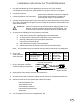
Safety Critical Components for XX93 Monitors. PRODUCT SAFETY NOTE: Components marked by the symbol ! have special characteristics important to safety. When replacing any of these components, be sure to use the parts specified in the parts list. An example of how the critical components are marked in the Master Part List is shown below. See the Master Part List for specifying critical components. ∆ Bd.# Part No. Bd. Sch. Ref.
Sicherheit Kritische Bestandteile für Monitoren XX93. PRODUKTSICHERHEIT ANMERKUNG: Bestandteile gekennzeichnet durch das Symbol ! haben Sie die speziellen Eigenschaften, die zur Sicherheit wichtig sind. Wenn Sie irgendwelche dieser Bestandteile ersetzen, seien Sie sicher, die Teile zu benutzen, die in der Stückliste spezifiziert werden. Ein Beispiel von, wie die kritischen Bestandteile in der Vorlagenstückliste gekennzeichnet werden, wird unten gezeigt.
CERONIX XX93 Monitor Part List A B C D E F CPA4233, 1493-CGA CPA4235, 1493-CGA CPA4200, 1493-VGA CPA4252, 1493-SVGA CPA4243, 1793-VGA CPA4244, 1793-VGA M N O P Q R G CPA4247, 1793-SVGA H CPA4250, 1793-SVGA I CPA4221, 1993-VGA J CPA4255, 1993-VGA K CPA4249, 1993-SVGA L CPA4256, 1993-SVGA ∆ Bd.# Part No. Bd. Sch. Ref. Description CPB1614 Main PCB “93” REV. E8 001 CPR0050 A1 J 0Ω, Jumper Wire 002 CPS1804 B1 EE2 8 Cond.
CERONIX XX93 Monitor Part List A B C D E F CPA4233, 1493-CGA CPA4235, 1493-CGA CPA4200, 1493-VGA CPA4252, 1493-SVGA CPA4243, 1793-VGA CPA4244, 1793-VGA G CPA4247, 1793-SVGA H CPA4250, 1793-SVGA I CPA4221, 1993-VGA J CPA4255, 1993-VGA K CPA4249, 1993-SVGA L CPA4256, 1993-SVGA ∆ Bd.# Part No. Bd. Sch. Ref. Description 043 CPR0016 A3 LL8 33KΩ ±5%, 1/4W, CF 043 CPR0017 A3 LL8 36KΩ ±5%, 1/4W, CF 043 CPR0018 A3 LL8 62KΩ ±5%, 1/4W, CF 043 CPR0145 A3 LL8 15.8KΩ ±1%, 1/4W, MF 043 CPR0153 A3 LL8 20.
CERONIX XX93 Monitor Part List A B C D E F CPA4233, 1493-CGA CPA4235, 1493-CGA CPA4200, 1493-VGA CPA4252, 1493-SVGA CPA4243, 1793-VGA CPA4244, 1793-VGA M N O P Q R G CPA4247, 1793-SVGA H CPA4250, 1793-SVGA I CPA4221, 1993-VGA J CPA4255, 1993-VGA K CPA4249, 1993-SVGA L CPA4256, 1993-SVGA ∆ Bd.# Part No. Bd. Sch. Ref. Description 081 CPC1032 B3 BB4 .01uF ±5%, 50V, Film 081 CPC1036 B3 BB4 .047uF ±5%, 50V, Film 081 CPC1040 B3 BB4 .015uF ±10%, 250V, Film 081 CPC1054 B3 BB4 .
CERONIX XX93 Monitor Part List A B C D E F CPA4233, 1493-CGA CPA4235, 1493-CGA CPA4200, 1493-VGA CPA4252, 1493-SVGA CPA4243, 1793-VGA CPA4244, 1793-VGA M N O P Q R G CPA4247, 1793-SVGA H CPA4250, 1793-SVGA I CPA4221, 1993-VGA J CPA4255, 1993-VGA K CPA4249, 1993-SVGA L CPA4256, 1993-SVGA ∆ Bd.# Part No. Bd. Sch. Ref.
CERONIX XX93 Monitor Part List A B C D E F CPA4233, 1493-CGA CPA4235, 1493-CGA CPA4200, 1493-VGA CPA4252, 1493-SVGA CPA4243, 1793-VGA CPA4244, 1793-VGA M N O P Q R G CPA4247, 1793-SVGA H CPA4250, 1793-SVGA I CPA4221, 1993-VGA J CPA4255, 1993-VGA K CPA4249, 1993-SVGA L CPA4256, 1993-SVGA ∆ Bd.# Part No. Bd. Sch. Ref. Description ! 154 CPD1264 J2 GG7 2A, 600V Fast D., FR205-F 155 CPC1003 J2 GG8 2,200pF ±20%, 1KV, Ceramic ! 156 CPD1264 J2 GG9 2A, 600V Fast D.
CERONIX XX93 Monitor Part List A B C D E F CPA4233, 1493-CGA CPA4235, 1493-CGA CPA4200, 1493-VGA CPA4252, 1493-SVGA CPA4243, 1793-VGA CPA4244, 1793-VGA M N O P Q R G CPA4247, 1793-SVGA H CPA4250, 1793-SVGA I CPA4221, 1993-VGA J CPA4255, 1993-VGA K CPA4249, 1993-SVGA L CPA4256, 1993-SVGA ∆ Bd.# Part No. Bd. Sch. Ref. Description 197 CPQ1307 E3 LL0 1.5A, 180V, NPN, 2SC4159E 197 CPR0050 E3 LL0 0Ω Jumper, 0.600” Long. 198 CPR0033 D3 MM0 30Ω ±5%, 1/4W, CF 198A CPD1264 D3 JJ5 2A, 600V Fast D.
CERONIX XX93 Monitor Part List A B C D E F CPA4233, 1493-CGA CPA4235, 1493-CGA CPA4200, 1493-VGA CPA4252, 1493-SVGA CPA4243, 1793-VGA CPA4244, 1793-VGA G CPA4247, 1793-SVGA H CPA4250, 1793-SVGA I CPA4221, 1993-VGA J CPA4255, 1993-VGA K CPA4249, 1993-SVGA L CPA4256, 1993-SVGA ∆ Bd.# Part No. Bd. Sch. Ref.
CERONIX XX93 Monitor Part List A B C D E F CPA4233, 1493-CGA CPA4235, 1493-CGA CPA4200, 1493-VGA CPA4252, 1493-SVGA CPA4243, 1793-VGA CPA4244, 1793-VGA G CPA4247, 1793-SVGA H CPA4250, 1793-SVGA I CPA4221, 1993-VGA J CPA4255, 1993-VGA K CPA4249, 1993-SVGA L CPA4256, 1993-SVGA ∆ Bd.# Part No. Bd. Sch. Ref. Description 270 CPD1251 B6 BB7 1N4148 Diode, Reverse Polarity. 271 CPD1251 B6 AA7 1N4148 Diode, Reverse Polarity.
CERONIX XX93 Monitor Part List A B C D E F CPA4233, 1493-CGA CPA4235, 1493-CGA CPA4200, 1493-VGA CPA4252, 1493-SVGA CPA4243, 1793-VGA CPA4244, 1793-VGA G CPA4247, 1793-SVGA H CPA4250, 1793-SVGA I CPA4221, 1993-VGA J CPA4255, 1993-VGA K CPA4249, 1993-SVGA L CPA4256, 1993-SVGA ∆ Bd.# Part No. Bd. Sch. Ref. Description 317 CPD1251 C7 EE7 10mA, 75V Diode, 1N4148 318 CPC1036 C6 FF8 .047uF ±5%, 50V, Film 318 CPR0050 C6 FF8 0Ω, Jumper Wire 319 CPD1251 C6 EE7 10mA, 75V Diode, 1N4148 320 CPR0012 C7 FF7 2.
CERONIX XX93 Monitor Part List A B C D E F CPA4233, 1493-CGA CPA4235, 1493-CGA CPA4200, 1493-VGA CPA4252, 1493-SVGA CPA4243, 1793-VGA CPA4244, 1793-VGA M N O P Q R G CPA4247, 1793-SVGA H CPA4250, 1793-SVGA I CPA4221, 1993-VGA J CPA4255, 1993-VGA K CPA4249, 1993-SVGA L CPA4256, 1993-SVGA ∆ Bd.# Part No. Bd. Sch. Ref. Description 360 CPR0153 C6 GG6 20.0KΩ ±1%, 1/4W, MF 361 CPR0157 D6 HH2 127KΩ ±1%, 1/4W, MF 362 CPR0171 D6 HH2 365KΩ ±1%, 1/4W, MF 362 CPR0180 D6 HH2 309KΩ ±1%, 1/4W, MF 363 CPR0034 D5 HH2 2.
CERONIX XX93 Monitor Part List A B C D E F CPA4233, 1493-CGA CPA4235, 1493-CGA CPA4200, 1493-VGA CPA4252, 1493-SVGA CPA4243, 1793-VGA CPA4244, 1793-VGA M N O P Q R G CPA4247, 1793-SVGA H CPA4250, 1793-SVGA I CPA4221, 1993-VGA J CPA4255, 1993-VGA K CPA4249, 1993-SVGA L CPA4256, 1993-SVGA ∆ Bd.# Part No. Bd. Sch. Ref. Description 394 CPR0390 E5 NN3 47Ω ±5%, 2W, MO 394 CPR0397 E5 NN3 33Ω ±5%, 2W, MO 395 CPR0050 E5 II1 0Ω, Jumper Wire 396 CPR0003 E5 JJ1 4.7Ω ±5%, 1/4W, CF 397 CPC1037 E5 JJ1 .
CERONIX XX93 Monitor Part List A B C D E F CPA4233, 1493-CGA CPA4235, 1493-CGA CPA4200, 1493-VGA CPA4252, 1493-SVGA CPA4243, 1793-VGA CPA4244, 1793-VGA M N O P Q R G CPA4247, 1793-SVGA H CPA4250, 1793-SVGA I CPA4221, 1993-VGA J CPA4255, 1993-VGA K CPA4249, 1993-SVGA L CPA4256, 1993-SVGA ∆ Bd.# Part No. Bd. Sch. Ref. Description 427 CPS1758 F5 OO2 .093” Dia. Bead Pin, YC2 427 CPS1759 F5 OO2 .062” Dia.
CERONIX XX93 Monitor Part List A B C D E F CPA4233, 1493-CGA CPA4235, 1493-CGA CPA4200, 1493-VGA CPA4252, 1493-SVGA CPA4243, 1793-VGA CPA4244, 1793-VGA G CPA4247, 1793-SVGA H CPA4250, 1793-SVGA I CPA4221, 1993-VGA J CPA4255, 1993-VGA K CPA4249, 1993-SVGA L CPA4256, 1993-SVGA ∆ Bd.# Part No. Bd. Sch. Ref. Description ! 443 CPC1050 H6 PP7 .47uF ±5%, 250V, Film ! 443 CPC1056 H6 PP7 .39uF ±5%, 250V, Film ! 443 CPC1059 H6 PP7 .33uF ±5%, 250V, Film ! 443 CPC1062 H6 PP7 .
CERONIX XX93 Monitor Part List A B C D E F CPA4233, 1493-CGA CPA4235, 1493-CGA CPA4200, 1493-VGA CPA4252, 1493-SVGA CPA4243, 1793-VGA CPA4244, 1793-VGA M N O P Q R G CPA4247, 1793-SVGA H CPA4250, 1793-SVGA I CPA4221, 1993-VGA J CPA4255, 1993-VGA K CPA4249, 1993-SVGA L CPA4256, 1993-SVGA ∆ Bd.# Part No. Bd. Sch. Ref. Description 503.5 CPR0151 G4 OO4 73.2KΩ ±1%, 1/4W, MF 503.5 CPR0158 G4 OO4 84.5KΩ ±1%, 1/4W, MF 504 CPR0147 G4 OO4 1.
CERONIX XX93 Monitor Part List A B C D E F CPA4233, 1493-CGA CPA4235, 1493-CGA CPA4200, 1493-VGA CPA4252, 1493-SVGA CPA4243, 1793-VGA CPA4244, 1793-VGA M N O P Q R G CPA4247, 1793-SVGA H CPA4250, 1793-SVGA I CPA4221, 1993-VGA J CPA4255, 1993-VGA K CPA4249, 1993-SVGA L CPA4256, 1993-SVGA ∆ Bd.# Part No. Bd. Sch. Ref. Description 811 CPR0510 N1 RR0 “K” PRA Video Amplifier 812 CPQ1301 N2 SS2 60V, .
CERONIX XX93 Monitor Part List A B C D E F CPA4233, 1493-CGA CPA4235, 1493-CGA CPA4200, 1493-VGA CPA4252, 1493-SVGA CPA4243, 1793-VGA CPA4244, 1793-VGA M N O P Q R G CPA4247, 1793-SVGA H CPA4250, 1793-SVGA I CPA4221, 1993-VGA J CPA4255, 1993-VGA K CPA4249, 1993-SVGA L CPA4256, 1993-SVGA ∆ Bd.# Part No. Bd. Sch. Ref. Description ! 854 CPC1076 N3 XX1 0.1uF ±5%, 200V, Film 855 CPR0371 N4 XX1 1KΩ ±5%, 1/2W, CF 856 CPR0366 N4 YY1 100KΩ ±5%, 1/2W, CF ! 857 CPC1034 N3 WW2 .
CERONIX XX93 Monitor Part List A B C D E F CPA4233, 1493-CGA CPA4235, 1493-CGA CPA4200, 1493-VGA CPA4252, 1493-SVGA CPA4243, 1793-VGA CPA4244, 1793-VGA G CPA4247, 1793-SVGA H CPA4250, 1793-SVGA I CPA4221, 1993-VGA J CPA4255, 1993-VGA K CPA4249, 1993-SVGA L CPA4256, 1993-SVGA ∆ Bd.# Part No. Bd. Sch. Ref. Description 899 CPD1250 N3 UU0 100mA, 200V Diode, FDH400 900 CPR0365 N3 WW0 470Ω ±5%, 1/2W, CF 900 CPR0371 N3 WW0 1KΩ ±5%, 1/2W, CF 901 CPC1040 N2 SS1 .
CERONIX XX93 Monitor Part List A B C D E F CPA4233, 1493-CGA CPA4235, 1493-CGA CPA4200, 1493-VGA CPA4252, 1493-SVGA CPA4243, 1793-VGA CPA4244, 1793-VGA M N O P Q R G CPA4247, 1793-SVGA H CPA4250, 1793-SVGA I CPA4221, 1993-VGA J CPA4255, 1993-VGA K CPA4249, 1993-SVGA L CPA4256, 1993-SVGA ∆ Bd.# Part No. Bd. Sch. Ref. Description 958 CPD1250 K3 TT7 100mA, 200V Diode, FDH400 959 CPD1250 K4 WW0 100mA, 200V Diode, FDH400 961 CPS1758 K4 YY1 .093” Bead Pin, Dag.
CERONIX XX93 Monitor Part List A B C D E F CPA4233, 1493-CGA CPA4235, 1493-CGA CPA4200, 1493-VGA CPA4252, 1493-SVGA CPA4243, 1793-VGA CPA4244, 1793-VGA M N O P Q R G CPA4247, 1793-SVGA H CPA4250, 1793-SVGA I CPA4221, 1993-VGA J CPA4255, 1993-VGA K CPA4249, 1993-SVGA L CPA4256, 1993-SVGA ∆ Bd.# Part No. Bd. Sch. Ref. Description Solder Conn. A2 NN7 Verrable Parabolic Pincushion Range. Q Solder Conn. C2 NN7 Verrable -Linear Pincushion Range. R S1 Solder Conn. F5 PP3 Raster Shift, One Unit. S2 Solder Conn.
VIDEO INTERFACE CIRCUIT, FUNCTION, DESCRIPTION (+ & - Analog). The particular mode of operation is selected by The video interface circuit is a general inserting jumpers, different value components, purpose RGB type input circuit. This circuit and solder bridges. The Production Assembly connects the external video signal to the video Drawings (PADs) are given in the appendix amplifiers. It can accept, DC or AC coupled which describe the component differences.
5.6V to 1.1V, NEGATIVE ANALOG, DC COUPLED, VIDEO INTERFACE CIRCUIT DESCRIPTION. Red Video Amp. Beam current Feedback Green Video Amp. Beam current Feedback Blue Video Amp. Beam current Feedback 0VDC Hs 56V 28,D3 SOCKET BOARD 800 TC11 CRT Focus EHT ARC PROTECT CRT Auto Bias V Sync Auto Bright ABA TC 10 TC 6 SOCKET BOARD CONNECTOR (TC) End Vertical Blanking Vertical O/S or Delayed Vertical O/S. TC7 Red TC5 Green TC 3 Blue Blanking & Beam Current Limit S FDH400 1.62K 604Ω 1.
0V to .7V, POSITIVE ANALOG, DC COUPLED, VIDEO INTERFACE CIRCUIT DESCRIPTION. To Video Board Blanking & Beam Current Limit S FDH400 TC7 Red TC5 Green TC 3 Blue T 1.62K 604Ω 1.21K 260 244 245 084 FDH400 VIDEO GAIN LINE U 1.62K 076 4-7VDC Vs 5-9Vpp 62,B4 Remote Control PCB +12V M. GAIN 1K 1K 062 RC2 485 2.7K 086 213 064 258 11.5-12.5V +12V GND FDH400 16 13 9 6 Ro Go Bo BBL 11 +A EN 10 +12V 5 TTL 3 - A BL 0Ω 15.8K* 1.87K 225 GR 15 0Ω 243 15.8K* 2.15K L 265 0Ω 233 242 84.
1Vp-p, POSITIVE ANALOG, AC COUPLED, VIDEO INTERFACE CIRCUIT DESCRIPTION. 16 13 9 6 R o G o Bo BBL 11 +A EN 10 +12V Controls 3 - A BL 5 TTL 12 M GAIN +12V 241 XRC5346A 4 GND R IN 2 RR 1 GIN 14 GR BIN 7 15 GND PN2222 BR 8 221 A5 B5 1N4937 J 225 K 1.87K 88.7Ω 223 226 A5 1N4937 233 2.15K 0Ω 100Ω 218 264 0Ω 219 1N4937 L 243 Black Level Adjustment is optional. 242 2.15K 10K 070 231 105Ω 232 2.
VIDEO AMPLIFIER CIRCUIT, FUNCTION, DESCRIPTION. The video amplifier, is a high speed push pull amplifier, which can swing as much as 90 volts. The maximum dynamic output swing is limited to 60 volts. The rest of the output voltage range is reserved for bias adjustment. 127V 120V VIDEO INTERFACE K2 K9 K34 K15 606Ω K19 B14 K16 885 16V 2SC3467 7 14 5.62K C5346 SIMPLIFIED VIDEO AMPLIFIER CIRCUIT: 1.50K 681Ω K1 K6 K6 836Ω OUTPUT MPS2907 NE592 K7 2SA1370 .015uF 40.
127V VIDEO AMPLIFIER SCHEMATIC. .1uF 957 Blue Video Amplifier 2 +12V K9 2SA 1370 B14 K16 K8 12 14 K36 150Ω 8 934 3pF 943 33 Ω 8 15Ω 6 K20 K21 A 681Ω 945 5.62K K6 K6 1N4148 21K 836Ω K35 K22 K10 K11 5 9 2.2K 12 K5 9 7 958 2SA 1370 K4 1.8K 955 1.8K 11 948 954 BIAS CONTROL LINE 3.32K GND 956 953 MPS2907 Dark screen 80-110VDC K12 FROM CA3224 +12V 1.8K VIDEO INTERFACE MG G Beam Current Feedback GND +12V R BLUE VIDEO TO CRT.
VIDEO BOARD POWER SUPPLY AND ARC PROTECT SCHEMATIC. +127fV +120V FDH 400 FDH 400 FDH 400 835 899 845 849 FDH 400 FDH 400 959 CC2 971 886 CC3 1/2W RED GREEN From Video Amp. From MAIN PCB G1 900 8 1/2W 6 851 11 12 1/2W BLUE 10 883 5 9 150Ω SOCKET 877 1/2W 880 1/2W 855 896 Focus 7 150Ω 1 1K 0Ω 1/2W 882 G2 10K 1/2W GND 100K 1.
CRT AUTO BIAS AND AUTO BRIGHT CIRCUIT, FUNCTION, DESCRIPTION. The auto bias circuit is a control system that forms a closed loop for controlling the CRT bias voltage. It generates a set of conditions where the current near the cutoff voltage of each gun is measured, and then adjusts the bias voltage of the video amplifiers, to set the correct black level voltage for each gun.
CRT AUTO BIAS AND AUTO BRIGHT CIRCUIT DESCRIPTION. The beam current feedback circuit uses a PNP video transistor 954 954 to direct most of the beam current to the auto bias circuit while passing the voltage waveform, from the video amplifiers to the CRT cathodes. Diode 956 insure that no video waveform 958 and capacitor 956 distortion occurs. An additional benefit of this circuit is that it protects the video amplifiers from the destructive 955 divide energy due arc energy.
CRT AUTO BIAS AND AUTO BRIGHT SCHEMATIC. 100K, 1/2W 856 FBT 2.2nF, 1KV 878 10K 1/2W 881 1K 873 855 330pF 1,000pF AUTO BRIGHT CIRCUIT 871 956 10 FDH400 VIDEO INTERFACE 1.8K 958 2SA1370 + 9 955 + C 5 6 4K 2,200pF 941 15 3 C11 4K C14 2,200pF 815 7 V. Osc. O/S .1uF 3 922 1.22.5V .1uF 4 923 5.76.3V 200Ω .047uF 1.22.5V 200Ω C16 5K 4 .1uF 6 C1 1 V. osc o/s or Delayed V. osc o/s V. Blanking 926 22K Filament Pls. 1 Bias active 891 18 8 .2.
Monitor, Block Diagram Review. G2≈290V On Video Board. GAME 2 For Dual Focus G1≈–20V VIDEO 3 VIDEO RGB VIDEO AMPS. 3 Interface SYNC V. & H. F.B.P. V retrace Beam limit M. gain High temp. limit I Interface J H VDY G H DY 3 EHT≈25KV D Beam current buffer CRT AUTO BIAS IC Program pulse Grid pulse Dynamic Focus used only on Dual Focus CRTs E F 2 Vs 3 VERTICAL SYNC DELAY CRT Feedback C Auto Bright H. sync (FBP) V.
BLANKING, MASTER GAIN, AND FAULT CIRCUIT, FUNCTION, DESCRIPTION. SIMPLIFIED GAIN CONTROL CIRCUIT: VIDEO INTERFACE C5346 GAIN SELECT RESISTORS +12V 1K MASTER GAIN 1K 062 485 FLYBACK PULSE 0VDC Hs 56Vpp 62,D6 LM393 2 210 072 To P/S OVP 1 1N4148 253 1/4 LM324 033 BEAM CURRENT LIMITER +6V 6 3 + Vertical Bias O/S 1/2 3 FAULT CIRCUIT VERTICAL BLANKING +2.5V HIGH Z To CRT 200Ω +7.5V PN2222 SIGNAL CONDITIONING CIRCUIT BIAS ACTIVE 3.6K Video Amp. One of three input circuits.
BLANKING, MASTER GAIN, AND FAULT CIRCUIT DESCRIPTION. The master gain control 485 is connected to the video gain line through a 1K resistor 062 . The voltage range of the video gain 062 064 , 076 076 line is programmable via resistors 064 and solder bridges at S , T , & U U. The solder bridges may connect resistors 244 , 245 244 245 , 258 , and 260 to the video gain line. This arrangement permits a variety of input signals and picture tubes to be used with the same monitor PCB.
BLANKING, MASTER GAIN, BEAM LIMITER, AND FAULT CIRCUITS SCHEMATIC. Remote control PCB VIDEO GAIN LINE 1K 4-7VDC Vs 4-9Vpp 61,B4 062 +12V MASTER GAIN RC2 1K 485 GND +12V VERTICAL BLANKING 6 MPS2907 1/2 LM393 7 212 + 210 6.8K 6.8K 0Ω 1N4148 211 253 5 4-7VDC Hs 4-9Vpp 61,B4 8 1/2 LM393 1 + 1K 1.8K 2 2.32.7V 3 1.8K 4 208 248 2-3VDC Vs 4Vpp 63,C4 (VERTICAL BIAS O/S) From LA7851 pin 16 368 4.5-5.3V Vs 5Vpp 16,E5 1.8K .
VERTICAL AND HORIZONTAL SYNC CIRCUIT DESCRIPTION. For Interlaced Vertical Sync. Composite Sync Vertical Sync { Horizontal Sync Sync Interface 2 Comparators + To LA7851 pin 19 Vertical Sync To Horizontal Cycle Synchronization and Composite Sync Decoder To LA7851 pin 1 Composite sync or separate vertical and horizontal sync are buffered by two comparators in the sync interface circuit. A vertical sync synchronization circuit is used to insure a stable raster and functions as a sync separator.
VERTICAL DEFLECTION CIRCUIT, FUNCTION, DESCRIPTION. The LA7851 IC is used for the vertical oscillator. The LA7838 is a vertical deflection control and high efficiency vertical yoke driver IC. Together they form a compact and efficient vertical deflection system.
VERTICAL DEFLECTION CIRCUIT DESCRIPTION. LA7838 HEAT SINK 378 Vertical Deflection 377 Ramp Reset One Shot out Tr. R/C out Ramp Gen. Reset Ramp Slope Vert. Drive V. size Control 50/60Hz Retrace Booster +12V +27V 1 Remote Control Board RC8 510Ω RC6 0Ω 2 3 4 5.5-6.4V Vs 3Vpp 21,D5 004 Vertical Size 500Ω 203 482 RC3 486 1,000pF 1K 483 8 5.5-6.5V Vs 1.4Vpp 23,F4 9 10 470uF 44.2K .01uF 402 374 380 393 1uF 401 392 GND 369 RC4 5-6VDC Vs 1.4Vpp 22,E5 7 68.
22-28V Vs .8Vpp 24,F7 VERTICAL DEFLECTION SCHEMATIC. Thermal Protection V.+12V Vert. Out Vertical Linearity Circuit DECREASES TOP AND BOTTOM VERT. SIZE. 196 Capacitor multiplier for the 2793. 200K 412 200K MPS2907 270Ω 2SC4159E 413 196 Boost GND 11 12 1N4005 I 13 0Ω 395 382 409 197 D5 D5 200K 200K H 371 372 PN2222 PN2222 .1uF 198 + 399 INCREASES TOP AND BOTTOM VERT. SIZE. 411 1.5-2.7V Vs 24Vpp 24,E4 30Ω 1N4005 199 373 1,000uF 119 GND 2SC3467 4.
HORIZONTAL DEFLECTION CIRCUIT DESCRIPTION. +12V Supply 5.4-6VDC 11, E5 3.92K 12 Remote Control PCB 484 1N4007 Horizontal SYNC INPUT 333 0Ω RC7 202 RC4 56pF 3 1.8K 7.3VDC Hs 5.5Vpp 01,D6 I1 17 2 2.7K I4 8 7 1 DELAYED SYNC O/S 2 NEG. 8.8K I3 I12 220uF 9 351 2. To be able to adjust the picture position, horizontally, with respect to the raster. 3. To operate stability through periods of missing horizontal sync pulses. 4.
HORIZONTAL DEFLECTION SCHEMATIC. 19 100Ω 20 I11 2.2nF 2SC5690 Horizontal 2 Drive Transformer 3 4 1 343 NO DVM Hs .9KVpp 27,G6 1N4007 1.2Ω Video Board 434 800 433 435 332 GND Fil. TC11 Fil. Rtn. TC12 Screen FOCUS EHT To Yoke 107V-127V LA7851 HORIZONTAL OSCILLATOR DISCHARGE 7 8 FLYBACK TRANSFORMER 092 EHT 415 H. V+ 9 3-7VDC Hs 5.5-6.3V Hs .2Vpp 07,E6 3.6Vpp 08,E6 10 10 092A 1K 10.8-12V 10, E6 451 5-6VDC Hs 7Vpp 09,E6 6 465 FOCUS 9 33K 13 14 I8 .
HORIZONTAL RASTER WIDTH CONTROL CIRCUIT DESCRIPTION. The purpose of the horizontal width control is to: 1. Provide a convenient means for adjusting the horizontal raster size. 2. Correct pincushion distortion in the vertical axis. 3. Correct horizontal raster distortion caused by periods of high beam current. The horizontal width control circuit is comprised of two main parts; The control circuit and the diode modulator (DM).
HORIZONTAL RASTER WIDTH AND POSITION CONTROL SCHEMATIC. Horizontal Raster Position Adjustment 22K 68Ω 1W 189 V+(+5V) 425 0Ω 4.7Ω 191 185 V+(-5V) S4 150Ω 1/2W SR 4.7Ω 0Ω 195 188 424 423 SL +6V 13 10.0K Vertical Yoke 022 12 023 1.2Ω 021 033 + + 100uF +6 Volt Source 100uF 026 026 GND HORIZONTAL YOKE 0Ω 10.0K 194 029 10.0K 10.0K 031 Horizontal Output FBT Pin 10 10 6V .33uF 10K 5 038 200K 6 3.3K 7 1/4 LM324 033 040 107V or 127VDC Hs 120Vpp 250Vpp 32,F6 Max.
DYNAMIC FOCUS CIRCUIT FUNCTION AND CIRCUIT DESCRIPTION. Model 1793-31.5DF 332 1 3 4 FLYBACK TRANSFORMER 1/2W, CC 13 470Ω 433 1N4007 520 VERTICAL DEFLECTION YOKE YC2 #2 FOCUS 452 434 426 FOCUS 9 SCREEN H PLL 8 DM Drive GND 7 5 OVP P/S Sync YC1 1,000uF 35V + 0Ω V+ 435 1.2Ω 12-18VDC Vs 50Vpp 29,F6 12 Dynamic Focus 0Ω 11 4 3 2 1 V- CPT1555 V+ Vs 2.2MΩ 2.2MΩ 510 1.00MΩ Vs 1.2Ω, 1W 385 Filament 453 2,200pF 1KV 13-15VDC Vs 3-5Vpp 31,F5 0VDC 1.6Vpp 465 Beam Current 504 .
Vertical Booster Amplifier Circuit, Circuit And Function Description. Monitors with vertical deflection current which exceeds 2.2 Ap-p cannot be driven directly by the LA7838 vertical deflection IC. The vertical booster amplifier circuit reduces the output current of the LA7838 by amplifying the vertical deflection current. The LA7838 is mounted on the vertical booster amplifier circuit board to allow the boosters circuit to be inserted at the output of the LA7838.
SIMPLIFIED POWER SUPPLY CIRCUIT, FUNCTION, DESCRIPTION. V+ +52V to +127V FLYBACK DIODE + AC line Res. GND LOAD H Dy & EHT VIDEO + 142 GND C5184 Error Amp. User supplied Isolation Transformer FET SECONDARIES Comp. + DRIVER V REF. V- 166 136 OSC. ENABLE 115 (-200V) The switching regulator includes the power FET 136 which passes current from V- to GND through the inductor 166 . During the time the FET is on, the current in the inductor is increasing and the inductor is storing energy.
SIMPLIFIED POWER SUPPLY CIRCUIT DESCRIPTION. The FET drive circuit avoids this problem by sensing flyback diode conduction. If the flyback diode conduction is sensed, the low current start mode is selected. This mode turns the FET on, to a current of .1A, for not more than 4uS.
SWITCH MODE POWER SUPPLY CIRCUIT DESCRIPTION. Oscillator waveform without sync: Oscillator waveform with sync: FET drive, C5184 pin 10: 115 , controls The series regulator IC 115 current to the monitor GND by pulse width 112 , has an modulation. A PNP transistor 112 emitter current, that is directly proportional to J1 and the 127V line voltage due to resistor J1 J14 .
SWITCH MODE POWER SUPPLY SCHEMATIC. V+ plus 20V ---Video Supply +24, 28V to Vertical Deflection. +16V, 18V to 12V Regulator. V+ plus 5V---H. Raster Shift V+ minus 5V---H. Raster Shift + 100uF JB -3V 120 193K J13 118 1N5954B 160V Zener 181 2SA1371E 100K + GND 1N4937 1N4937 121 122 171 6.5-7.5VDC 41,D1 3 167 2.2nF JC +1.5V 130Ω 150 J15 FR205 V+ J4 56pF 108 107 3 4 3.4-4.2VDC 104 See Table 105 106 REMOVE FOR 230V 103 33.2K 62K 143A 144 152 250V 163 5.7-6.
Equipment Setup For Repairing The Model XX93 Monitor. +17.1 DVM ISOLATION 115 VAC OSCILLOSCOPE TRANSFORMER No DVM 320Vpp 40,G1 ISOLATED DUAL 1A DC POWER SUPPLY 1-4VDC 12Vpp 50,E2 0 to 30V 0 to 30V VARIABLE TRANSFORMER Test Generator or Signal Source No. LTR.No. X X XYV X-Y VDC CERONIX Model XX93 Legend Description the XX93 board part number. The parts list gives the { Represents CERONIX PART NUMBER which is indexed to the board part number.
Ausrüstung Gegründet Für Die Reparatur Des Monitors Des Modells XX93. +17.1 DVM LOKALISIERUNG 115 VAC OSZILLOGRAPH TRANSFORMATOR No DVM 320Vpp 40,G1 LOKALISIERTE DOPPEL 1A GLEICHSTROM VERSORGUNGSTEIL 1-4VDC 12Vpp 50,E2 0 to 30V 0 to 30V VARIABLER TRANSFORMATOR Prüfen Sie Generator oder Signalquelle No. LTR.No.
POWER SUPPLY, TROUBLE SHOOTING TIPS. SAFETY FIRST; Use only one hand when working on a powered up monitor to avoid electrical shock. Always wear safety glasses. Many of the failures that cause burnt components and boards are eliminated by the load sensitive switching mode power supply in the CERONIX monitor. This feature can cause problems with servicing the monitor if the proper trouble shooting approach is not used.
Trouble Shooting Handbook The information that is written in this handbook is to help repair XX93 Monitors. Here is a guideline in which this handbook will follow: 1. 2. Color problems. No video with power. 3. No V-H sync. 4. 5. Retrace lines. No power. Always wear safety glasses. Caution; Use only one hand when working on a powered up monitor to avoid electrical shock. Color Problems.
Problem Excessive color. Turn down G2 (bottom pot of FBT) if excessive color is too bright. Refer to the schematic for the specific pin numbers of each color. Tests should preformed in order to reduce chance of replacing wrong component. Problem Tests Probable Solution 1. Turn down M. Gain. Measure voltage of K-Film pin 1 for each color. If affected color has a .3V difference then others Desolder pin 1. Make open to trace. If pin 1 still different replace K-Film. 846 . 2. Measure voltage across cap.
Problem Retrace Lines . Problem Monitor Shuts Down. Tests Probable Solution 1. Turn down M. Gain to minimum. 927 Measure voltage, auto bias IC 927 pins 2, 4, & 6 for 5.5V to 6.5V. Also measure voltage, pins 3, 5, & 7 for 1.1V to 2.7V 2. Measure voltage, LM324 920 pin 5. Should be less than 4.5V. If old style C-Film (no solder connection) & pin 5 voltage is 4.8V add a 7.15K resistor pins 8 to 11. Otherwise replace C-Film. 215 ) 3. Check video gain line (J 215 215 , .
Filament Voltage Test. When replacing either the flyback transformer or the video board, the filament voltage may not be correct. Measuring the filament voltage is not accurate using a true RMS voltage meter, because of the high frequency components, which make up the filament voltage. An oscilloscope, with RMS capability, may be used to measure the filament voltage.
HeizfadenSpannung Test. Wenn der EHT-Transformator oder die Videokarte geändert wird, kann die Heizfadenspannung falsch sein. Die Heizfadenspannung besteht aus Hochfrequenzbestandteilen. Genaues Messen der Heizfadenspannung kann nicht mit einem Effektivwertmeßinstrument erhalten werden. Ein Oszillograph mit Effektivwertmessen-Fähigkeit kann benutzt werden, um die Heizfadenspannung zu messen.
SETUP AND CONVERGENCE PROCEDURE 1. Use a knife to brake free the magnetic rings on the yoke, which are usually locked with red varnish. Bring the adjustment tabs on each pair of magnetic rings in line for the starting point. 2. Loosen the yoke clamp. Remove the yoke wedges and the tape from the CRT. 7. Adjust the yoke position, on the CRT neck, to the center of purity.
SETUP UND KONVERGENZ PROZEDUR 1. Benutzen Sie eine scharfes Messer, um die magnetischen Ringe auf dem Joch frei zu bremsen, die normalerweise mit rotem Lack gesperrt werden. Holen Sie die Justagetabulatoren auf jedem Paar magnetischen Ringen in der Zeile für den Ausgangspunkt. 2. Lösen Sie den Klemmring des Jochs. Löschen Sie die Jochkeile von der CRT. Löschen Sie das Band von der CRT. 3. Schließen Sie einen Testgenerator an den videoinput an. 4. Schalten Sie den Monitor ein.
CERONIX, INC. 13350 New Airport Road Auburn, California 95602-7419 Tel. (530) 886 - 6400 Fax. (530) 888 - 1065 WEB. www.ceronix.com REPLACEMENT PARTS PURCHASE ORDER FORM Date Requisition No. Purchase Order No. Name BILL TO SHIP TO STREET & N0. STREET & N0. CITY STATE ZIP CITY STATE ZIP Fax No. Phone No. Shipping Information Comments CERONIX Part No. Description 1 2 3 4 5 6 7 8 9 10 11 12 Please copy form and fill in, parts order, on copy.
DEGAUSSING COIL ATTACHMENT SPECIFICATION. For The Model 1493 Video Monitor. Use degaussing coil part number CPS1766. ATTACH THE GROUNDING STRAP FIRST. With the degaussing coil leads centered on the bottom of the CRT, FORM THE COIL to avoid the remote control board. INSTALL A WIRE TIE through the top hole in the left CRT ear. INSTALL A WIRE TIE through the top hole in the right CRT ear. INSTALL WIRE TIES through the bottom hole in the left CRT ear.
Degaussing Coil & Grounding Strap Attachment Specification. For The Model 1793, 1993, 2093 Video Monitor. 1. The first item to attach to the picture tube is the grounding strap. Lay the tube face down on a soft surface. Slide the folded over end of the braided wire over the top left CRT mounting ear (The braided wire is oriented to the left). Attach the spring at the other end to the left hole of the right bottom mounting ear. 2. Next attach the degaussing coil.
Degaussing Coil & Grounding Strap Attachment Specification. For The Model 2793 and 3693 Video Monitor. 1. The first item to attach to the picture tube is the grounding strap. Lay the tube face down on a soft surface. Slide the folded over end of the braid over the left top CRT mounting ear. Attach the spring at the other end to the, right side top, slot in the rimband. Pull the bare wire through the bottom slot in the rimband (tension the spring) and back around the braid.
Highpot, For Shock Hazards, Circuit Description. For the models 1493,1793, 1993, 2093, 2793, and 3693 video monitors. It is the responsibility of the company which uses the Ceronix monitor in there system to make sure that no shock hazards exist. Below is a description of the highpot test to verify that the monitor is properly connected to an isolation transformer. Once the monitor is installed in the enclosure, the protective earth ground connection must be connected.
Highpot, Für Schock Gefahren, StromkreisBeschreibung. Für die Modelle 1493,1793,1993,2093,2793, und 3693 videomonitoren. Es ist die Verantwortung der Firma, die den Ceronix Monitor in dort system benutzt, sich zu vergewissern, daß kein Schock Gefahren existieren. Unten ist eine Beschreibung Prüfung des highpot zu beglaubigen, daß der Monitor ordentlich an einen Isolierung Umformer angeschlossen wird.
Wire Routing Instructions. Attach the protective earth, green / yellow, ground wire. Fold remote cable to clear CRT and add wire tie. Rout yoke wires over CRT neck. Shorten EHT wire and add wire tie. Rout G2 wire around CRT socket, shorten with loop, and add wire tie. 108 Plug in video board. Fold video flat cable to avoid contacting the metal frame. Secure fold with a wire tie. Shorten focus wire and add wire tie. Finished assembly with the different voltage type wires not touching each other.
Precision Resistor Arrays (PRAs). Make solder connection CA when using these C PRAs for replacement parts on the XX92 product line. Ω 200Ω C13 Ω 200Ω C8 Ω 200Ω C16 2 1 Program PULSE H. Blank 68.1K 68.1K 68.1K C1 C2 C3 1.82 K C5 C6 CA 2.74K 1.82 K C7 Ω 900Ω C17 3 4 5 6 7 Program RED i Beam GREEN i Beam Program PULSE BLUE i Beam PULSE 20K 8 GND 5.00K 4K 4K 4K C10 C11 C4 C14 5.00K C9 5.00K C12 C15 9 10 11 12 13 14 15 16 17 18 19 20 NC 12V LINE 4.
Precision Resistor Arrays (PRAs). 1 2 3 5 4 6 7 8 9 10 11 12 13 14 15 16 17 18 19 20 K A - Increases Output Voltage by 10V 1.62K 0Ω 21K K22 K33 606Ω 820Ω K1 A K7 7 6 5 4 2 3 1 C 5.62K K11 K9 689Ω K34 1N4148 K35 E B 1.2K NE592 3904 K10 1.49 K K6 40.2K 9 8 1N4148 K36 K8 K32 10 11 12 14 13 K19 150Ω 100Ω 2.2K K3A K21 K5 15Ω 301Ω 3.32K 150Ω 33Ω K2 VIDEO INPUT K4 K3B +12V LINE +16V LINE NPN B GND NPN E 9.
Precision Resistor Arrays (PRAs). 1 2 3 5 4 6 7 8 9 10 11 12 13 14 15 16 17 18 19 20 BLUE A - Increases Output Voltage by 10V 1.29K 0Ω 21K K22 K33 606Ω 820Ω K1 A K7 7 6 5 4 2 3 1 C 5.62K K11 K9 689Ω K34 1N4148 K35 E B 1.2K NE592 3904 K10 1.49 K K6 40.2K 9 8 1N4148 K36 K8 K32 10 11 12 14 13 K19 150Ω 100Ω 2.2K K3A K21 K5 15Ω 240Ω 3.32K 150Ω 33Ω K2 VIDEO INPUT K4 K3B +12V LINE +16V LINE NPN B GND NPN E 9.
3 2 1 4.7Ω, 607607 606 606 4.7Ω, 608608 3.3Ω, 610 1W 610 1.2Ω,605 1W 605 611 611 FR205 NPN 602 PNP 601 E C B E C B V W X X Y CPM2501 Y Z Z CPM2002 x3 CPM2005 x3 CPM2501 x3 VERTICAL DEFLECTION BOOSTER ASSEMBLY CERONIX CPA4267 Complete Assembly View (Top view) HEATSINK CPM2141 CABLE: CABLE:CPS1858 CPS1858 NPN 603 E C B Board Assembly View (Component side) 13 12 11 10 9 8 7 6 5 4 3 2 1 612, LA7838 LA3838 Vertical Amp.
The "Drive Signals To The Monitor Input" form is included here for those people who have problems interfacing their drive electronics with the Ceronix Monitor. DRIVE SIGNALS to the MONITOR INPUT voltage and waveforms, work sheet. CERONIX 13350 New Airport Road Auburn, CA, USA 95602-7419 Fax (530) 888-1065 VIDEO: Company name: Date: For CERONIX Monitor Model number: For the following measurements use an oscilloscope.
DECLARATION OF CONFORMITY Manufacturer: C. CERONIX 13350 New Airport Road Auburn, California 95602 USA Equipment: Component Color Monitor. Models: 1493-CGA, 1493-VGA, 1493-SVGA. 1793-VGA, 1793-SVGA. 1993-VGA, 1993-SVGA. 2093-CGA, 2093-VGA. 2793-CGA, 2793-VGA. 3693-CGA. Component Isolation Transformer Assembly. Models: ISOXFR-75W, ISOXFR-100W. Standards: IEC 60950, 3rd Edition 'National Differences: AT, AU, CA, DE, ES, FR, GB, HU, RU, US, ZA.
Models: ISO XFR-75W ISO XFR-100W SAFETY ISOLATING TRANSFORMER 115
Circuit Function Description. The basic function of the ISO XFR-75W and ISO XFR-100W is to isolate the line power for monitors requiring an isolation transformer. The transformer is designed to have a low leakage flux value which allows it to be mounted close to the CRT. To accomplish the low leakage flux, the transformer has two sets of primary and secondary coils mounted on a modified toroid type core.
Brown L PC1 T506 7 PTC 1N4007 T502 TZL200B 200Vz T512 2.7Ω ±10%, 1W, CC 2 1N4007 T508 T511 T509 1N4742A T514 12Vz T515 Blue L PC3 T501 RED WHT BLU WHITE PC1 120VAC output to monitor. BLACK PC2 GRY T520 ! 1 127K, ±1% 1/4W, MF ORG 2.2nF 1KV IRF520 T505 ! Isolation Transformer 3 4 1N4007 T510 365K, ±1% 1/4W, MF YEL T517 T519 T504 0Ω Screw BRN 2.2nF 1KV ! 33K, ±5% 1/4W, CF 0.1uF 250V 6 5 T507 1.5uF, 400V T503 120 or 240VAC, 50-60Hz input power. 6Ω, .
Stromkreisfunktion Beschreibung Die grundlegende Funktion des XFR75W und des XFR100W ist, die Zeile Energie für die benötigenden Monitoren und Lokalisierung Transformator zu lokalisieren. Der Transformator wird entworfen, um einen niedrigen Durchsickernflusswert zu haben, der erlaubt, daß er nah an der CRT eingehangen wird. T vollenden den niedrigen Durchsickernfluß, hat der Transformator zwei Sets der Primär- und Sekundärspulen, die an einem geänderten Ringkörperartkern eingehangen werden.
WARNING! Grounding of the monitor is to be evaluated in the end user application. Installation Instructions. 1. Mount the unit on a, grounded, flat metal surface using at least two screws. Note; The mounting surface should not have holes larger than 0.2" diameter under the enclosure. 2. Connect the mains cable to the Molex plug mounted on the enclosure. 3. Connect the output cable from the unit to the monitor power input connecter. AVERTISSEMENT.
INSTALLATION of the ISO XFR-75W, ISO XFR-100W ISOLATION TRANSFORMERS. Connector: AC Line or neutral AC Line Mains power. Preferred orientation for optimum cooling. CERONIX CHASSIS. The ISO XFR-75W/-100W MUST be grounded by mounting on a grounded, conductive surface via at least two screws. WARNING: Mains power and ground connections must be made before power is applied to the ISO XFR-75W or the ISO XFR-100W Isolation Transformers.
INSTALLATION Isolierung Transformator des XFR75W und des XFR100W. Stecker: Wechselstromzeile oder -neutrales. WechselstromZeile. Hauptlinie Spannung Lagebestimmung Prefered für das optimale Abkühlen. CERONIX CHASSIS. Das XFR75W und das XFR100W müssen geerdet werden, indem man an einer geerdeten, leitenden Oberfläche mit mindestens zwei Schrauben einhängt.
Model ISO XFR-75W Specifications. Electrical: Rating; Input Notes: Output Volts; 120VAC 108VAC to 132VAC 108VAC to 146VAC Volts; 240VAC 216VAC to 264VAC 108VAC to 146VAC Volts; 120VAC 108VAC to 132VAC 216VAC to 292VAC Volts; 240VAC 216VAC to 264VAC 216VAC to 292VAC 50Hz to 60Hz 50Hz to 60Hz Frequency Power 100VA Capacitance } Output wired for 240VAC. Input = output. No Load. 75VA Full Load. 250pF input to output. Highpot Voltage Environmental: Output wired for 120VAC. 0VA .
Model ISO XFR-100W Specifications. Electrical: Rating; Input Volts; 120VAC 108VAC to 132VAC 108VAC to 146VAC Volts; 240VAC 216VAC to 264VAC 108VAC to 146VAC Volts; 120VAC 108VAC to 132VAC 216VAC to 292VAC Volts; 240VAC 216VAC to 264VAC 216VAC to 292VAC 50Hz to 60Hz 50Hz to 60Hz Frequency Power 1.24 Watts Maximum Environmental: Output wired for 120VAC. } Output wired for 240VAC. Input = output. No Load. 100VA Full Load. 275pF input to output.
Equipment setup for trouble shooting the ISO XFR-75W, ISO XFR-100W Isolation Transformers. Use only one hand when working on a powered up ISO XFR-75W, ISO XFR-100W to avoid electrical shock. SAFETY FIRST; Always wear safety glasses when working on powered up electronic equipment. Mains Power VARIABLE 2A Fuse Ground TRANSFORMER 100W 120V 100W 120V ISOLATION Isolation transformer, wired for 240VAC output. Note; ISO XFR-75W, ISO XFR_100W output wired for 120VAC.
Vorrichtungen haben zum Lösen von Problemen mit dem 75W und dem 100W Isolierung Transformatoren benutzt. SICHERHEIT ZUERST: Um elektrischen Shock zu vermeiden, benutzen Sie nur eine Hand beim Arbeiten auf einem angeschaltenen Transformator 75W oder 100W. Tragen Sie immer Sicherheitsgläser beim Arbeiten auf angeschaltener elektronischer Ausrüstung.
ISO XFR-75W, ISO XFR-100W Schematic (Manual Voltage Select). Shield 3A Fuse CPR0425 Brown L PC1 Screw BLK T506 ! YEL / GRN 7 6 5 BRN ! Switch 0Ω Shown In 240VAC Input Mode T518 T519 2 ! ORG Isolation Transformer RED 3 4 T501 Screw WHITE YEL 120 or 240VAC, 50-60Hz input power. 0Ω WHT Blue L PC3 PC1 120VAC output to monitor. BLACK BLU PC2 GRY OPTIONAL WIRING. WHITE YEL PC1 240VAC output to monitor. ORG RED BLACK BLU PC2 ISO XFR-75W, ISO XFR-100W Assembly Drawing.
Parts List Addendum.
Parts List Addendum.
Parts List Addendum.
Parts List Addendum.