
User's Manual


The
Beam Current Buffer converts the, high impedance low current, beam
current signal into a low impedance voltage. This voltage is applied to the auto
bias IC through a 200 ohm resistor. After the three lines of beam current are
measured, the program pulse from the auto bias IC, produces a voltage drop
across this 200 ohm resistor that equals the amplitude of the beam current
voltage.
A
B
C
D
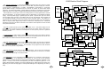
Refer to the block diagram on page 15 (foldout) when reading this description.
9
The Video Interface is designed around a custom IC and will accept DC or AC
coupled positive analog video signals. It can also be used with negative analog
and 4 line TTL. This IC has a built in multiplier circuit for the master gain
control and blanking functions. Resistors are used to protect the IC and to set
the gain. The programmed gain is dependent on the input signal amplitude
except with the TTL mode. Solder jumpers and component substations are used
to program the Video Interface for the type of input signal to be received. The
output of the IC drives the video amplifiers. This drive is a current where 0 mA
is black and 10 mA is a saturated color.
The Video Amplifiers are of the push pull type. They are built partly on thick
films and partly on the video PCB. Spreading out the amplifier reduces the
component heat and improves the life of the unit. The bandwidth is 25 MHz with
40Vp-p output. The rise and fall times are 20nS.
The Beam Current Feedback circuit directs most of the beam current of each
amplifier to the beam current buffer. The only time this current is measured, by
the auto bias circuit, is during the time of the three faint lines at the top of the
screen and three lines thereafter. The CRT auto bias circuit is designed to adjust
the video amplifier bias voltage such that the beam current of each of the three
guns is set to a specific programmed value.