
User Manual

• Never discharge batteries below 3V per cell under load. For Tattu series batteries which are used for Unmanned Aircraft system, The recommended cut off voltage is 3.5V per cell
• Never allow the temperature of batteries to exceed 140°F during discharge. Adequate cooling for batteries is required, especially when discharging at or near maximum rates.
• Never discharge batteries a voltage below that which is recommended by the manufacturer when measured under load (i.e. connected to a vehicle or charger capable of discharge).
Batteries discharged to lower than the lowest approved voltage provided by the manufacturer may be damaged, resulting in a loss of performance and/or potential fire.
This product contains a circuit board, which utilizes a small amount of power in order to monitor the battery’s condition. As a result, it is recommended to
check the battery’s power level every 3 months. If you plan to store the battery for a prolonged period of time, it is recommended to keep the lower level at 3
bars.
Circuit Board Functions:
Product overview:
This battery contains a function that warns against abnormal voltages. See the table below for more details:
The circuit board measures the remaining power level of the battery according to its cell voltages and displays the remaining power left with 4 indicator lights around the button. A short press
of the button will display the remaining battery power. See the table below for specific display details. Please note that the battery indicator lights are used for reference only and may not be
perfectly accurate. For exact voltage values, it is recommended to use a more accurate measuring instrument.
This battery has a built-in mechanism that prevents the product from overcharging. When the battery’s circuit board detects the voltage of any cell being
greater than or equal to 4.4 ±0.025V, the circuit board will trigger overcharge-prevention mechanism, which will send a signal to the battery charger to
disrupt and stop the charging. The charger will then display: “Connection Break / Connection Error” or something similar to indicate the issue. Please note
that this prevention mechanism can only be triggered when the main battery’s charging cable and balance connector are connected correctly into a LiPo
battery charger. In addition, the LiPo charger being used must have the ability to detect the connection status of the battery by reading its cell voltages.
Please note: This battery does not have an overcharge protection circuit that will automatically cut off the internal battery power. This battery is not recom-
mended for those looking for a built-in active overcharge-protection circuit board.
LED1 solid red → Low voltage warning
When the battery cell voltage is lower than 3.2V, the low voltage warning will be triggered. LED1 light will always be solid red. Please stop using this battery as it has been over discharged.
Please use a voltage checker or a charger with voltage detection function to check the voltage of each cell. If the voltage of each cell is higher than 3.0V, please try using a LiPo charger for
balance charging. The recommended charging current is 0.2C. If charging doesn’t work, please stop using this battery. If the battery cell voltage is lower than 3.0V, it means that the battery
has been extremely over-discharged and maybe internally damaged and it is not recommended to continue use.
LED1 alternating red and blue flashing → Large cell voltage difference warning
When the voltage difference between the cells is greater than 300mV, the warning against a large cell-voltage difference will be triggered, and LED1 will alternate between flashing red and
blue. Please stop using this battery and contact the manufacturer.
LED1 flashing red → Overcharge warning
When a charger fails, the battery can be overcharged. If the battery cell voltage is greater than or equal to 4.4±0.025V, it will trigger the overcharge warning. Please stop charging the battery
immediately and disconnect all charging cables from the battery. Do not use the charger to charge other batteries. The charger may be faulty. If you continue to use this charger it may cause
an overcharge condition of any battery and a fire may result.
Please note:when the overcharge prevention mechanism is triggered, LED1 will keep flashing red until the prevention mechanism is cancelled. During overcharge, it will not be possible to
read the battery cell voltage using the battery’s balancing connector. If you need to read the voltage from the battery’s balancing connector, you will need to cancel the battery overcharge
prevention mechanism. There are two ways to clear this condition:
1. Automatic cancellation mechanism: When the voltage of all battery cells is lower than 4.35V, the overcharge prevention mechanism will be automatically cleared.
2. Manual cancellation: If you need to manually cancel the overcharge prevention mechanism, you will need to press and hold the button for 5 seconds. After pressing the button for 5 seconds, the overcharge
prevention mechanism will be cancelled. After the prevention mechanism is manually cancelled, please do not recharge the battery. If you short press the button again and the battery cell voltage is still greater than
or equal to 4.4V, the red light of LED1 will flash again, and it will automatically go out after flashing for five seconds. If the voltage is lower than 4.4V, the LED indicator will display the normal power level.
• Never discharge Batteries at amperage rates higher than specified on Batteries’ labels.
• Never leave batteries unattended during the discharge process. During the discharge process, the user should constantly monitor the process in case any potential issues occur.
• In case of emergency, discontinue the process immediately, disconnect the battery, place it in a safe area, and observe it for approximately one hour. This may cause the battery to leak and
the reaction with air may cause the chemicals to ignite, resulting in a fire. A safe area should be outside of any building or vehicle and away from any combustible materials. A battery can still
ignite even after one hour.
• The user must check the battery condition before use or discharge. Immediately stop using the battery if cells are discovered to be imbalanced or if cells are puffed or leaking.
Discharging
The circuit board will not work, thus not triggering the prevention mechanism, in the following conditions:
1. The battery is incorrectly connected to the charger
2. The battery’s balance connector is not connected to the charger
3. The charger does not have the ability to detect whether the charging cable and balance connector are properly connected
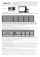
LED1
Button
LED2
LED3
LED4
3S
LED1
LED2
LED3
LED4
4S/6S
Button
All instructions and precautions must be read carefully and followed exactly before use. Warning: With improp-
er operation, It is possible to create a serious fire, damage your device, create property and collateral damage
and serious injury. If an unexpected error occurs, please take immediate action to reduce possibly bodily harm
and/or property damage.
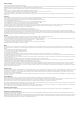
LED Indicator Lights - Status Details
Status LED1(Red/Blue)
Solid Blue
LED2(Blue) LED3(Blue) LED4(Blue)
Capacity 1-10% (3.21-3.4V/cell)
Capacity 11-40% (3.41-3.755V/cell)
Capacity 41-70% (3.755-4.0V/cell)
Capacity 71-100% (4.0-4.35V/cell)
Solid Blue
Solid Blue
Solid Blue
Solid Blue
/ / /
/ /
/
Solid Blue
Solid Blue
Solid Blue
Solid Blue Solid Blue
LED Abnormal Indicator Lights - Status Details
Status LED1(Red/Blue)
red and blue flashing
LED2(Blue) LED3(Blue) LED4(Blue)
Large cell voltage difference warning
(greater than 3.0V)
Overcharge warning
(greater than or equal to 4.4 ± 0.025V/cell)
Low voltage warning (lower than 3.2V/cell)
flashing red
solid red
/ / /
/ / /
/ / /