Warranty First Year Warranty The Gentec-EO thermal power and energy detectors carry a one-year warranty (from date of shipment) against material and /or workmanship defects when used under normal operating conditions. The warranty does not cover recalibration or damages related to misuse. Gentec-EO will repair or replace at its option any wattmeter or joulemeter which proves to be defective during the warranty period, except in the case of product misuse.
Version 5.0 II TABLE OF CONTENTS WARRANTY .................................................................................................................... I First Year Warranty ....................................................................................................................................................i Lifetime Warranty ........................................................................................................................................................
Version 5.0 III LIST OF ILLUSTRATIONS FIG. 1-1 DB-15 CONNECTOR PIN-OUT ...................................................................................................................2 FIG. 1-2 BNC CONNECTOR ......................................................................................................................................3 FIG. 1-3 MOLEX CONNECTOR PIN-OUT IN E0 VERSION ..................................................................................3 FIG.
Version 5.0 1 1 ULTRA SERIES UP POWER DETECTORS 1.1 INTRODUCTION The Gentec-EO Ultra Series UP power detector family includes eleven series (XLP12, UP12E, UP17P, UP19K, UP25N(M), UP25T, UP50N(M), UP55N(M), UP55C, UP60N(M), UP55G, and UP60G) of opto-thermal sensors with different cooling options (stand alone, heat sink, fan and water), with or without amplification. The high power surface absorber sensors are designed for use at high average power densities.
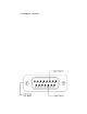
Version 5.0 2 1.2 POWER DETECTOR CONNECTORS 1.2.1 DB-15 “intelligent” connector The DB-15 male "intelligent" connector contains an EEPROM (Electrically Erasable Programmable Read-Only Memory) with different information such as the model of the detector, the calibration sensitivity, the applicable scales and the wavelength correction factor for up to 20 wavelengths related to the Ultra Series UP detector head in use.
Version 5.0 3 1.2.2 Integra USB connector The Integra USB Connector is an integrated monitor that allows to plug the head directly into a computer. It has the same serial commands as the MAESTRO and a few extra one’s (see the PCGentec-EO Manual) and uses the same PC-Gentec-EO software. All specifications are mostly the same, except for: Wattmeter and joulemeter heads have a noise ~1.3 x higher. The risetime of the UP12 head (with anticipation) is slower by 0.2 seconds. 1.2.
Version 5.0 4 1.2.5 Molex connector (MT version) The Molex male connector, available in the UP with amplification, allows you to power the internal circuit board (PCB) and to read the signal with your own electronics. The PCB needs +12 to +16V from a regulated power supply but does not need negative voltage. FIG. 1-4 MOLEX CONNECTOR PIN-OUT IN MT VERSION FIG. 1-5 MOLEX CONNECTOR PIN-OUT IN MT-B VERSION Make your own molex cable for use with OEM heads. Product number : 202170 FIG.
Version 5.0 5 1.2.6 Molex-BNC (BT version) The Molex-BNC connection, available in the UP with amplification, allows you to power the internal circuit board (PCB) with the Molex connector and to read the signal with the BNC connector (load impedance : 10 MΩ). The PCB needs +12 to +16V from a regulated power supply but does not need negative voltage. FIG. 1-7 MOLEX CONNECTOR PIN-OUT IN BT VERSION Ultra Series UP Instruction Manual Gentec Electro-Optics Inc.
Version 5.0 6 1.2.7 Molex connector without amplification or anticipation (M0 version) The Molex male connector, available in the UP without amplification, allows you to read the signal with your own electronics. FIG. 1-8 MOLEX CONNECTOR PIN-OUT IN M0 VERSION 1.2.
Version 5.0 7 1.3 ULTRA SERIES UP, XLP SERIES SPECIFICATIONS The following specifications are based on a one-year calibration cycle, an operating temperature of 15 to 28°C and a relative humidity not exceeding 80%. Storage 10 to 65°C and relative humidity not exceeding 90%.
Version 5.0 …12-…-3S-VP XLP12-3S-VP Effective Aperture Diameter Spectral Range Calibrated spectral range Power Noise Level c, d Thermal Drift e Typical Rise time (0-95%) Typical sensitivity 12 mm 0.248 – 20 µm 0.248 – 2.5 µm b ± 0.5 µW 12 µW/oC 30 s (3.0 s with anticipation) 220 mV/W ± 2.5 % @ 1.064µm ± 3.5 % @ 0.25-2.5µm ±2% ± 0.5 % ± 0.5 % 3W Calibration Uncertainty Linearity with Power Repeatability (Precision) Power Resolution Max. Average Power Max.
Version 5.0 UP10K-2S-H5-L Effective Aperture Diameter Spectral Range Calibrated spectral range a Power Noise Level Typical Rise time (0-95%) Typical sensitivity Calibration Uncertainty Linearity with Power Repeatability (Precision) Power Resolution Max. Average Power Max. Average Power (1 min) (cooling : minimum 3 min) Max. Average Power Density b 1.064 µm, 2W CW 10.6 µm, 2W CW Pulsed Laser Damage Thresholds 1.064 µm, 360 µs, 5 Hz 1.
Version 5.0 UP12E-…-H5-… Effective Aperture Diameter Spectral Range Calibrated spectral range a Power Noise Level Typical Rise time (0-95%) Typical sensitivity Calibration Uncertainty Linearity with Power Repeatability (Precision) Power Resolution Max. Average Power Max. Average Power (1 min) (cooling : minimum 3 min) Max. Average Power Density b 1.064 µm, 10W CW 10.6 µm, 10W CW Pulsed Laser Damage Thresholds 1.064 µm, 360 µs, 5 Hz 1.
Version 5.0 11 UP17P-6S-H5 UP17P-6S-H5 Effective Aperture Diameter Spectral Range Calibrated spectral range a Power Noise Level b Typical Rise time (0-95%) Typical sensitivity c Calibration Uncertainty d Linearity with Power Repeatability (Precision) Power Resolution Max. Average Power Max. Average Power (1 min) (cooling : minimum 3 min) 17 mm 190 nm – 20 µm 0.248 – 2.5 µm and 10.6 µm 1 mW 2.5 s (0.8 s with anticipation) 0.6 mV/W ± 2.5 % ±2% ± 0.5 % ± 0.5 % 6W Max. Average Power Density e 1.
Version 5.0 12 UP17P-6S-W5 UP17P-6S-W5 Effective Aperture Diameter Spectral Range Calibrated spectral range a Power Noise Level b Typical Rise time (0-95%) Typical sensitivity Calibration Uncertainty c Linearity with Power Repeatability (Precision) Power Resolution Max. Average Power Max. Average Power (1 min) (cooling : minimum 3 min) Max. Average Power Density d 1.064 µm, 10 W CW Pulsed Laser Damage Thresholds 1.064 µm, 150 µs, 5 Hz 1.
Version 5.0 UP19K-…-Hx-… Effective Aperture Diameter Spectral Range Calibrated spectral range a Power Noise Level Typical Rise time (0 - 95 %) Typical sensitivity Calibration Uncertainty Linearity with Power Repeatability (Precision) Power Resolution Max. Average Power Max. Average Power (1 min) (cooling : minimum 3 min) Max. Average Power Density b 1.064 µm, 10W CW 10.6 µm, 10W CW Pulsed Laser Damage Thresholds 1.064 µm, 360 µs, 5 Hz 1.
Version 5.0 UP19K-15S / 30H -VR Without PCB 18 mm 0.266 - 2.5 µm 0.30 – 2.5 µm 2 mW 36 s (2.5 s with anticipation) 0.34 mV/W ± 2.5 % ±2% ± 0.5 % ± 0.5 % 15S: 15 W 30H: 30 W 15S: 20 W 30H: 35 W UP19K-…-VR-… Effective Aperture Diameter Spectral Range Calibrated spectral range a Power Noise Level Typical Rise time (0 - 95 %) Typical sensitivity Calibration Uncertainty Linearity with Power Repeatability (Precision) Power Resolution Max. Average Power Max. Average Power (1 min.) (cooling : minimum 3 min) Max.
Version 5.0 UP19K-…-W5-… UP19K-15S / 30H / 50L / 50F / 50W / 50DI -W5 Without PCB Effective Aperture Diameter Spectral Range Calibrated spectral range a Power Noise Level Typical Rise time (0-95%) 1 mW 5 s (1.4 s with anticipation) Typical sensitivity 0.65 mV/W Max.
Version 5.0 UP25N(M)-…-Hx… 16 UP25N-40S / 100H -H9 UP25N-250F-H12 UP25M-350W-H12 Without PCB Aperture Diameter Spectral Range Calibrated spectral range a UP25N-40S / 100H -H9 UP25N-250F-H12 UP25M-350W-H12 With PCB 25 mm 190 nm - 20 µm 0.248 – 2.5 µm and 10.6 µm Power Noise Level H9: 3 mW H12: 10 mW Typical Rise Time (0 – 95 %) H9: 5 s (1.3 s with anticipation) H12: 7.9 s (1.3 s with anticipation) Typical sensitivity H9: 0.23 mV/W H12: 0.
Version 5.0 UP25T-…-Hx-… Aperture Diameter Spectral Range Calibrated spectral range a Power Noise Level Typical Rise Time (0-95%) Typical sensitivity Calibration Uncertainty Linearity with Power Repeatability (Precision) Power Resolution Max. Average Power Max. Average Power (1 min.) (cooling : minimum 3 min) Max. Average Power Density b 1.064µm, 10W CW 10.6 µm, 10W CW Pulsed Laser Damage Thresholds 1.064 µm, 360 µs, 5 Hz 1.
Version 5.0 UP50N(M)-…-W9... UP50N-40S / 50H -W9 UP50M-50W -W9 Without PCB Aperture Diameter Spectral Range Calibrated spectral range a Power Noise Level Typical Rise Time (0 – 95 %) 5 mW 16 s (3.5 s with anticipation) Typical sensitivity 0.12 mV/W Calibration Uncertainty Linearity with Power Repeatability (Precision) Power Resolution Max. Average Power Max. Average Power (1 min.) (cooling : minimum 3 min) Max. Average Power Density 1.064µm, 10W CW Pulsed Laser Damage Thresholds 1.
Version 5.
Version 5.0 20 Specifications subject to change without notice. UP55N(M)-…-VR-… UP55N-50S/100H/150F-VR UP55M-200W-VR Without PCB Aperture Diameter Spectral Range Calibrated spectral range a Power Noise Level UP55N-50S/100H/150F-VR UP55M-200W-VR With PCB 55 mm 300 nm – 2.5 µm 0.30 – 2.5 µm 15 mW Typical Rise Time (0 - 95 %) 4s 50 s (without anticipation) 5 s (with anticipation) Typical sensitivity 0.
Version 5.0 UP55C-2.5KW-HD Effective Aperture Diameter Spectral Range Calibrated spectral range a Power Noise Level Typical Rise time (0 - 95 %) Typical sensitivity Calibration Uncertainty Linearity with Power Repeatability (Precision) Max. Average Power Max. Average Power Density 1.064 µm, 500W CW 1.064 µm, 1500W CW 1.064 µm, 2500W CW Pulsed Laser Damage Thresholds 1.064 µm, 7 ns, 10 Hz 532 µm, 7 ns, 10 Hz a b 21 UP55C-2.5KW-HD Without PCB 55 mm 0.19 µm - 20 µm 0.248 – 2.5 µm and 10.6 µm ± 0.2 W 3.
Version 5.0 UP55G-…-HX-… UP60G-…-HX-… UP55G-500F-H12 UP55G-600F-HD Without PCB Aperture Diameter Spectral Range Calibrated spectral range a 55 mm Power Noise Level Typical Rise Time (0 – 95 %) Typical sensitivity Calibration Uncertainty Linearity with Power Repeatability (Precision) Power Resolution Max. Average Power Max. Average Power (1 min.) Max. Average Power Density b 1.064 µm, 10 W, CW 1.064 µm, 500 W, CW Pulsed Laser Damage Thresholds 1.064 µm, 360 µs, 5 Hz 1.
Version 5.0 23 700 600 The absorber will be damaged if it is used in this zone Power [W] 500 400 300 Safe zone (If the applied power does not exceed the maximum power in the specification) 200 100 0 0 2 4 6 8 Beam diameter [mm] 10 12 FIG. 1-10 MINIMUM BEAM SIZES FOR UP WITH H-TYPE ABSORBER AT 1.064 µM. Ultra Series UP Instruction Manual Gentec Electro-Optics Inc.
Version 5.0 24 1.4 UP CALORIMETER MODE SPECIFICATIONS The UP Ultra Series has an optional mode that is called calorimeter mode. It allows you to measure single shot pulse energy. This mode is accessible when you use a UP with a Gentec-EO monitor or with your own data acquisition system. For more information, refer to the monitor’s instruction manual or call Customer Support at Gentec-EO, see p. ii, Contacting Gentec Electro-Optics Inc.
Version 5.0 Typical sensitivity Power sensitivity / Energy sensitivity Typical rise time in calorimeter mode Minimum repetition period Maximum pulse width Maximum measurable energya Noise equivalent energy Accuracy 25 UP55G, UP60G -…H12 UP55M, UP55G, UP60M, UP60G -…HD mV/J 0.013 0.008 J/W 4.62 4.46 ms 1800 1600 sec 14.3 12 ms 433 430 J 200 200 mJ 250 250 % ±5 ±5 a For 1,064 µm ; 360 µs pulses.
Version 5.0 26 1.5 UP POTENTIOMETER POSITIONS The UP with amplification has 3 holes on top of the detector for the UP12E, UP19K and the UP25T and on the left side of the detector for the UP25N(M), UP50N(M), UP55N(M) and the UP60N(M) giving access to the potentiometers to adjust the gain, the anticipation and the offset, as shown in figure 1-8. WARNING : If you are using Gentec-EO calibration, DO NOT change the potentiometer settings because this would invalidate factory calibration. FIG.
Version 5.0 27 1.6 USING A CUSTOMER-SUPPLIED HEAT SINK This is a special case. Standard detectors are calibrated and shipped complete with a Gentec-EO heatsink or back module installed. However, should the customer wish to install an alternative heatsink or back module, the following indications should be followed. This does not apply to the XLP, UP_P, UP_T, UP_M, and UP_G series. Instructions : 1. Required specifications for customer-supplied back module are given in Fig 1-10 through 112.
Version 5.0 28 FIG. 1-12 TAPPED HOLE POSITIONS FOR UP12E, WITHOUT PCB FIG 1-13 TAPPED HOLE POSITIONS FOR UP19K Ultra Series UP Instruction Manual Gentec Electro-Optics Inc.
Version 5.0 29 FIG 1-14 TAPPED HOLE POSITIONS FOR UP25N, UP50N(M), UP55N(M), AND UP60(M) Ultra Series UP Instruction Manual Gentec Electro-Optics Inc.
Version 5.0 30 2 OPERATING INSTRUCTIONS In order to ensure a long lifetime of accurate measurements, it is recommended that UP wattmeters be held within the following ambient conditions stated in the specifications. For a fan-cooled UP, connect the fan to the proper power supply. NOTE: The UP55G and UP60G must only be used with the Gentec-EO Power Supply P/N 201103. For a water-cooled UP, connect the detector head to a an cooling water supply. The water-cooled UP is equipped with ¼’’ tube fittings .
Version 5.0 31 2.1 WITH ANY GENTEC-EO MONITOR To make a measurement Gentec-EO monitor, continue with the following steps: 4. Connect the detector head to the input socket on the monitor (see the monitor’s instruction manual). 5. Block off the detector head to prevent it from sensing heat from random sources. 6. Once the reading is thermally stable, the reading should be set to 0 W with the monitor’s Zero (Offset) function (see the monitor’s instruction manual). 7.
Version 5.0 32 Measured power[W] = (output voltage[V] - zero level voltage[V]) / calibration sensitivity[V/W] = 1000 x (Vout[mV] - Vzero level[mV]) / calibration sensitivity[mV/W] 2.3 SAFETY OPERATION NOTES Diffusive surfaces When using the UP with a coating H, W, and VR be aware of the diffused back reflection: - H and W: ~ 5-15% VR: ~ 40-45% As on any diffusive surface, the light on the sensor coating is scattered more or less uniformly as a Lambertian diffuser.
Version 5.0 33 Appendix A: WEEE directive 1.1 Recycling and separation procedure for WEEE directive 2002/96/EC: This section is used by the recycling center when the detector reaches its end of life. Breaking the calibration seal or opening the monitor will void the detector warranty. The complete Detector contains 1 Detector with wires or DB-15. 1 instruction manual 1 calibration certificate 1 Electronic PCB (Integra option) 1 Plastic enclosure (Integra option) 1.
Version 5.0 34 DECLARATION OF CONFORMITY Application of Council Directive(s): Manufacturer’s Name: Manufacturer’s Address: 2004/108/EC EMC Directive Gentec Electro Optics, Inc. 445 St-Jean Baptiste, suite 160 (Québec), Canada G2E 5N7 Representative’s Name: Representative’s Address: Laser Component S.A.S 45 bis Route des Gardes 92190 Meudon (France) Type of Equipment: Model No.
Version 5.0 35 Appendix B: Using the XLP12 with the XLP12 filter: The XLP12 filter features ease of installation and removal. To use an XLP12 series wattmeter (@ any wavelength) with the XLP12 filter, the user must calibrate the assembly using the following procedure: Step 1: Set up the XLP12 wattmeter without the filter to measure the power of your laser. Adjust the sensitivity of the wattmeter to your working wavelength.
Version 5.0 36 Appendix C: Using the XLP12 with an optical fiber adaptor: When fitted with an appropriate adaptor, such as Gentec-EO’s FC Optical Fiber Connector, the XLP12 can be used to measure the output of an optical fiber. When using an optical fiber adaptor, it is the user's responsibility to ensure that the entire output of the fiber is incident upon the detector's absorbing surface. Figure 1-10 and the following inequation are provided as a guide to verify this. FIG.