
User Manual


Version 5.0
Ultra Series UP Instruction Manual Gentec Electro-Optics Inc. All rights reserved
11
a
The calibrations at 2.1 to 2.5 µm and 10.6 µm are on special request only.
a
Nominal value, actual value depends on electrical noise in the measurement system.
c
Maximum output voltage = sensitivity x maximum power
d
Including linearity with power
e
See graph at the end of this section
Specifications subject to change without notice.
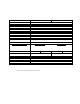
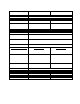
UP17P-6S-H5
UP17P-6S-H5
Effective Aperture Diameter
17 mm
Spectral Range
190 nm – 20 µm
Calibrated spectral range
a
0.248 – 2.5 µm and 10.6 µm
Power Noise Level
b
1 mW
Typical Rise time (0-95%)
2.5 s (0.8 s with anticipation)
Typical sensitivity
c
0.6 mV/W
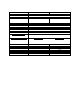
Calibration Uncertainty
d
± 2.5 %
Linearity with Power
± 2 %
Repeatability (Precision)
± 0.5 %
Power Resolution
± 0.5 %
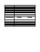
Max. Average Power
6 W
Max. Average Power (1 min)
(cooling : minimum 3 min)
7 W
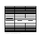
Max. Average Power Density
e
1.064 µm, 10 W CW
10.6 µm, 10 W CW
36 kW/cm
2
11 kW/cm
2
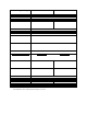
Pulsed Laser Damage Thresholds
1.064 µm, 360 µs, 5 Hz
1.064 µm, 7 ns, 10 Hz
532 nm, 7 ns, 10 Hz
266 nm, 7 ns, 10 Hz
Max. Energy Density
5 J/cm
2
1.0 J/cm
2
0.6 J /cm
2
0.3 J /cm
2
Peak Power Density
14 kW/cm
2
143 MW/cm
2
86 MW/cm
2
43 MW/cm
2
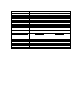
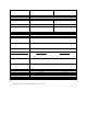
Dimensions (mm)
46H x 46 (W) x 10.7 (D)
Weight (head only)
0.1 kg
Recommended load Impedance
100 kΩ
Output Impedance
N.A.
Linearity vs beam dimension
± 0.5 %
PCB electrical supply
N.A.
Max output signal
N.A.