User’s Manual Purifier® HEPA Filtered Enclosures & Purifier® Class I Filtered Enclosures Models 3980200, 3980201, 3980202, 3980203, 3980220, 3980221, 3980222, 3980223, 3980300, 3980301, 3980302, 3980303, 3980320, 3980321, 3980322, 3980323, 3980400, 3980401, 3980402, 3980403, 3980420, 3980421, 3980422, 3980423 Register your product online at www.labconco.com/productreg.
For more information, please contact us: ExpotechUSA 10700 Rockley Road Houston, Texas 77099 USA 281-496-0900 [voice] 281-496-0400 [fax] E-mail: sales@expotechusa.com Website: www.ExpotechUSA.
Labconco HEPA Filtered Enclosure Manual Warranty Labconco provides a warranty on all parts and factory workmanship. The warranty includes areas of defective material and workmanship, provided such defect results from normal and proper use of the equipment.
TABLE OF CONTENTS CHAPTER 1: INTRODUCTION About This Manual Typographical Conventions 1 2 3 CHAPTER 2: PREREQUISITES Support, Vibration & Movement Requirements Location and Air Current Requirements Exhaust & Blower Requirements Electrical Requirements Space Requirements 5 6 6 6 7 7 CHAPTER 3: GETTING STARTED Unpacking Your Enclosure Installing the Filtered Enclosure on a Supporting Structure and Work Surface Connecting to the Exhaust System (Optional) Installation of HEPA Filters and Accessory OdorContr
Prohibited Acid Use 38 CHAPTER 6 MAINTAINING YOUR FILTERED ENCLOSURE Routine Maintenance Schedule Decontamination Determination of when to Replace HEPA Filters How to Install a New HEPA Filter HEPA Filter Leak Test Setting the Inflow Face Velocity with the Speed Control Adjustment Calibrate and Operate the Airflow Monitor Determination of When to Replace Odor control Carbon Filters and How to Replace Calculating Odor control Carbon Filter Life Initial Certification Re-Certification Fluorescent Light Repla
CHAPTER 1 INTRODUCTION Congratulations on your purchase of a Labconco Purifier® HEPA Filtered Enclosure or Purifier® Class I Filtered Enclosure. Your enclosure provides personnel protection through superior containment. It is the result of Labconco’s more than 50 years experience in manufacturing fume hoods and more than 30 years experience in manufacturing filtered enclosures. These enclosures will effectively contain toxic, noxious, or biohazardous particulates when properly installed and operated.
Chapter 1: Introduction particulates, and nuisance powders, Labconco recommends the use of the Purifier HEPA Filtered Enclosure. See chart below and contact Labconco for additional ordering information. No. 1. 2. 3. 4.
Chapter 1: Introduction Chapter 5: Using Your Filtered Enclosure discusses the basic operation of how to prepare, use and shut down your filtered enclosure. Chapter 6: Maintaining Your Filtered Enclosure explains how to perform routine maintenance on the filtered enclosure. Chapter 7: Accessorizing Your Filtered Enclosure explains acceptable modifications to the filtered enclosure or how to add accessories.
Chapter 1: Introduction • • 2' 4 3' ☞ • 4' • with the information following an exclamation icon may result in injury to the user or permanent damage to the enclosure. Critical information is presented in boldface type in paragraphs that are preceded by the wrench icon. A trained certifier or contractor should only perform these operations. Failure to comply with the information following a wrench icon may result in injury to the user or permanent damage to your hood.
CHAPTER 2 PREREQUISITES Before you install the filtered enclosure, you need to prepare your site for installation. You must be certain that the area is level and of solid construction. In addition, a dedicated source of electrical power should be located near the installation site to power the filtered enclosure, and other apparatus. Additionally, the enclosure should be strategically placed in the lab to provide efficient workflow.
Chapter 2: Prerequisites Support, Vibration and Movement Requirements At a minimum, the supporting structure usually consists of a base cabinet and chemically-resistant work surface. • A stand or mobile bench is not recommended if the enclosure will be used for precise weighing of powders. Location and Air Current Requirements The Purifier Filtered Enclosures have been designed to contain hazards by negating typical cross drafts and turbulence within the opening.
Chapter 2: Prerequisites Enclosure Width 2' Model Description 2' Purifier Class I Enclosure 2' Purifier HEPA Filtered Enclosure 3' 3' Purifier Class I Enclosure 3' Purifier HEPA Filtered Enclosure 4' 4' Purifier Class I Enclosure 4' Purifier HEPA Filtered Enclosure Face Velocity (fpm) 60 75 80 90 100 105 60 75 80 90 100 105 60 75 80 90 100 105 Exhaust Volume (CFM) 85 110 115 130 145 155 130 165 175 200 220 230 175 220 235 265 295 310 Noise Pressure db(A) 48-53 49-55 50-56 51-57 53-58 54-59 48-53 52
Chapter 2: Prerequisites 8
CHAPTER 3 GETTING STARTED Now that the site for your filtered enclosure is properly prepared, you are ready to unpack, inspect, install, and validate your system. Read this chapter to learn how to: • Unpack and move the enclosure. • Set up the enclosure with the proper supporting structure and work surface. • Connect to an exhaust system if applicable. • Installation of HEPA and accessory Odor Control carbon filters. • Connect the electrical supply. • Set the face velocity with the speed control adjustment.
Chapter 3: Getting Started Unpacking the Enclosure The United States Interstate Commerce Commission rules require that claims be filed with the delivery carrier within fifteen (15) days of delivery. Carefully remove the shrink-wrap or carton on the enclosure and inspect it for damage that may have occurred in transit. If damaged, notify the delivery carrier immediately and retain the entire shipment intact for inspection by the carrier. ☞ DO NOT RETURN GOODS WITHOUT THE PRIOR AUTHORIZATION OF LABCONCO.
Chapter 3: Getting Started 0.36" of the front of the work surface. Mounting holes are provided in the Labconco accessory work surfaces to secure the enclosure. Work Surface Specifications The work surface should be smooth, rigid, and durable, such as a chemical-resistant epoxy resin. The surface should be non-porous and resistant to the biohazards, powders, solvents and chemicals used in conjunction with the Purifier Filtered Enclosure.
Chapter 3: Getting Started Figure 3-1 Filtered Enclosure Installation 12
Chapter 3: Getting Started Connecting to the Exhaust System (Optional) ! WARNING: The weight of the exhaust ductwork system must be supported independently of the enclosure superstructure or damage may occur. The exhaust system should be installed by a qualified HVAC contractor. Exhaust transition kits aid in the removal of chemicals or applications where a higher degree of biohazard and particulate removal is required.
Chapter 3: Getting Started Figure 3-2 Exhaust Duct Connection Kit shown installed on Purifier Models (Optional) Kit #3924400 (2'), 3924401 (3'), and 3924402 (4') 14
Chapter 3: Getting Started Installation of HEPA Filters and Accessory Odor Control Carbon Filters HEPA Filters HEPA HEPA filters are shipped installed with the gasket on the downstream side. The HEPA filters are leak checked at Labconco. A second leak check is recommended before using the enclosure and at least annually thereafter. Consult your Safety Officer and Chapter 6 for the HEPA Filter Leak Test. See Figure 4-2 for HEPA filter location, HEPA filter gasket, and filter clamp bolts.
Chapter 3: Getting Started HEPA Carbon Carbon Carbon Filter Type HEPA 2' 3707900 3' 3707901 4' 3707902 Organic Vapor Activated Carbon 2' 3937200 3' 3937300 4' 3937400 Appropriate Use HEPA filters are high-efficiency particulate air filters having a particulate removable efficiency of 99.99% for particles with a diameter of 0.3 micron. Adsorbs organic compounds designated by NIOSH guidelines as acceptable for use with chemical cartridge-type respirators.
Chapter 3: Getting Started Set the Face Velocity with the Speed Control Adjustment Adjustment of the speed control gives the correct face velocity and is located behind the front panel. The face velocity should be from 75 to 105 fpm for biohazardous operations. (Consult your Safety Officer for airflow recommendations for your application). Containment is maximized at a setting within this range. Working at the lowest face velocity appropriate for the application will give the quietest operation.
Chapter 3: Getting Started The Purifier Enclosures were also subjected to Biological Containment testing, using a modified Personnel Protection Test, as described in NSF/ANSI Standard Number 49. An aerosol challenge of approximately 5 x 10⁸ spores of Bacillus subtilus var Niger were released in the enclosure and appropriate air sampling equipment established the number of spores that escaped through the sash opening. Each size enclosure was tested three times.
CHAPTER 4 HIGH PERFORMANCE FEATURES AND SAFETY PRECAUTIONS High Performance Features: The patented* Purifier HEPA Filtered Enclosure and Purifier Class I Enclosure are designed to meet the needs of the laboratory scientist, and provide superior containment while operating at velocities between 75-105 feet per minute. The filtered enclosures have been tested to effectively contain toxic, noxious, and biohazardous materials when properly installed and operated.
Chapter 4: High Performance Features and Safety These concentrations of materials are predominantly removed on the “first pass” of airflow through the chamber resulting in high performance containment. The plenum and the HEPA filter are jacketed by negative pressure. Should a leak occur in the filter gasket or the plenum, the contaminated air is recaptured and refiltered. The Purifier Class I Enclosure and Purifier HEPA Filtered Enclosure have an access port located behind the front panel.
Chapter 4: High Performance Features and Safety 17 26 16 19 15 10 3 8 18 2 4 6 1 5 Not Shown 7, 9, 10, 11, 12, 13, 20, 21, 22, 23, 24, 25, 28 (See Figure 4-2) Figure 4-1 21
Chapter 4: High Performance Features and Safety Figure 4-2 HEPA Filtered Enclosure Airflow Diagram 22
Chapter 4: High Performance Features and Safety 1. Aerodynamic Clean-Sweep™ Air Foil has a unique shape that allows air to sweep the work surface for maximum containment. The Clean-Sweep™ openings create a constant protective barrier from contaminants. Should the operator inadvertently block the airflow entering the air foil, air continues to pass under the air foil and through the Clean-Sweep openings. See Figures 4-1 and 4-3. Figure 4-3 2.
Chapter 4: High Performance Features and Safety 3. Upper Dilution Air Supply provides bypass air from above the work area. This feature constantly bathes the inside of the sash with clean air and reduces powders, particulate materials and chemical fumes along the sash plane, near the critical breathing zone. Five to seven percent of the required air volume is introduced through the upper dilution air supply. The upper dilution air supply also reduces stagnant pockets of air in the upper interior.
Chapter 4: High Performance Features and Safety Monitor is an available option on all Purifier models. See Figure 4-1 and 4-2. 11. Inherently Safe Impeller has a negative pressure plenum that surrounds the positive pressure impeller so that if a leak should occur, the unfiltered air is captured and refiltered. See Figure 4-2. 12. Vibration-Isolated Motorized Impeller has vibration isolation supports, which eliminates transfer of vibration to the work surface.
Chapter 4: High Performance Features and Safety 21. Lamp Ballast (Not Shown) for the fluorescent lamp is located behind the control panel. 22. UV (Ultraviolet) Lamp (Not Shown), found only on Purifier Class I Enclosure, allows the operator to surface disinfect the work area of the enclosure when it is not in use. The UV will not penetrate the plane of the sash and lower airfoil. 23. Accessory Work Surface (Not Shown) is dished and contoured to fit the dimensions of the enclosures to contain spills. 24.
Chapter 4: High Performance Features and Safety Safety Precautions 1. Although the enclosure has been engineered to maintain optimum operator safety, caution should always be used while working. Prior to using the enclosure, check to make sure that the exhaust blower is operating and that air is entering the enclosure at its specified face velocity. The use of an airflow monitor is recommended to alert the user to a problem with airflow. 2. Use good housekeeping in the enclosure at all times.
Chapter 4: High Performance Features and Safety 11. The use of safety goggles, protective clothing, gloves and any other personal protective equipment recommended by your safety officer should be used. 12. The sash must remain in the down position while using the enclosure. 13. Proper performance of the enclosure depends largely upon its location and the operator’s work habits. Consult the references in Appendix D. 14.
Chapter 4: High Performance Features and Safety 19. The HEPA filter in the enclosure will gradually accumulate airborne particulate matter from the room and from work performed in the enclosure. The rate of accumulation will depend upon the cleanliness of the room air, the amount of time the enclosure is operating and the nature of work being done in the enclosure. With normal usage, the HEPA filters will last two to five years before requiring replacement. 20.
Chapter 4: High Performance Features and Safety 28. Only nuisance powders, biohazardous and particulates removed by HEPA filters and trace chemicals which can be safely adsorbed and treated with specific carbon based filters are appropriate for use in this enclosure. 29. The warning properties (i.e., odor, taste) of the volatile organic compounds or other material being used in the enclosure must be adequate to provide an early indication that the carbon filter may be saturated or inadequate.
CHAPTER 5 APPROPRIATE APPLICATIONS FOR YOUR FILTERED ENCLOSURE Now that the installation of your filtered enclosure is completed, you are ready to use your filtered enclosure. Read this chapter to learn about: 1. Routine Daily Work Procedures. 2. Suitable Applications. 3. Appropriate HEPA Filter Applications, Suitability and Guidelines. 4. Odor Control Carbon Filter Applications. 5. Definition of Terms. 6. Appropriate Chemicals for Odor Control Carbon Filters. 7.
Chapter 5: Using Your Filtered Enclosure and Appropriate Application • Arrange for minimal disruptions, such as room traffic or entry into the room while the enclosure is in use. Start-up • Turn on exhaust system and accessory light. Turn off the UV light, if equipped. • Only raise the sash for loading and cleaning. • Check the baffle air slots for obstructions. • Allow the enclosure to operate unobstructed for 1 minute. • Wear a long sleeved lab coat and rubber gloves. Use protective eyewear.
Chapter 5: Using Your Filtered Enclosure and Appropriate Application Unloading Materials and Equipment • Objects in contact with contaminated material should be surface decontaminated before removal from the enclosure. • All open trays, weigh vessels or containers should be covered before being removed from the enclosure. Shutdown • Turn off the exhaust system and light. • Turn off the UV light, if applicable.
Chapter 5: Using Your Filtered Enclosure and Appropriate Application be ducted to the outside. The surface of the HEPA filter is fragile and should not be touched. Care must be taken to avoid puncturing the HEPA filter during installation. If you suspect that a HEPA filter has been damaged, DO NOT use the enclosure. See Chapter 6 for Replacing the HEPA Filter. • • The HEPA filter will gradually accumulate airborne particulate matter from the room and from work performed in the enclosure.
Chapter 5: Using Your Filtered Enclosure and Appropriate Application THOSE USED AS GUIDELINES FOR THIS PRODUCT. IT IS THE USER’S RESPONSIBILITY TO BECOME AWARE OF LOCAL REGULATIONS GOVERNING THE SAFE USE AND DISPOSAL OF CHEMICALS, CARBON AND HEPA FILTERS. KNOWLEDGE OF ESTABLISHED SAFE EXPOSURE LEVELS IS IMPERATIVE TO THE PROPER USE OF FILTERED ENCLOSURES. Definition of Terms NIOSH – National Institute for Occupational Safety and Health/Mine Safety and Health Administration. (U.S.A.
Chapter 5: Using Your Filtered Enclosure and Appropriate Application IDLH (Immediately Dangerous to Life and Health). An atmosphere that poses an immediate hazard to life or produces immediate irreversible health effects. IDLH concentrations should not be approached in the enclosure. Appropriate Chemicals for Odor Control Carbon Filters Below is a general set of rules to determine appropriateness of chemical usage.
Chapter 5: Using Your Filtered Enclosure and Appropriate Application Hazardous Misapplications for Odor Control Carbon Filters with Volatile Chemicals There is one scenario where the accessory carbon filter misapplication would be a part of a hazardous condition. If the user continues to operate the enclosure with any of the following conditions present a potentially hazardous condition will exist: 1. The inlet concentration of vapors is greater than the TWA. 2. The carbon filter becomes saturated. 3.
Chapter 5: Using Your Filtered Enclosure and Appropriate Application Consult a Labconco Technical Specialist for estimated saturation life. See Chapter 6 for an example of estimating saturation life. Another source is the Labconco chemical guide for carbon filtered enclosures. Prohibited Acid Use The Purifier HEPA and Purifier Class I filtered enclosures motorized impeller cannot be exposed to acids.
CHAPTER 6 MAINTAINING YOUR FILTERED ENCLOSURE Monitoring airflow and changing the filters is the primary maintenance required. Decontamination may be required and is reviewed in Chapter 6. Certification and recertification is reviewed in Chapter 6. Review this chapter on maintenance for the following: 1. Routine Maintenance. 2. Decontamination. 3. Determination of when to replace the HEPA filters. 4. How to install a new HEPA filter. 5. HEPA filter leak test. 6.
Chapter 6: Maintaining Your Filtered Enclosure Routine Maintenance Schedule Weekly • Wipe down the interior surfaces of the enclosure with a disinfectant or cleaner, depending upon the usage of the unit and allow to dry. • Using a damp cloth, clean the exterior surfaces of the enclosure, particularly the front and top to remove any accumulated dust. • Operate the exhaust system, noting the airflow velocity through the enclosure using a source of visible smoke.
Chapter 6: Maintaining Your Filtered Enclosure Annually • Replace the fluorescent lamps. Replace UV lamps if equipped. • Have the enclosure validated by a qualified certification technician. See Certification and Recertification in Chapter 6. • All monthly activities.
Chapter 6: Maintaining Your Filtered Enclosure How to Install a New HEPA Filter NOTE: The enclosure must be properly decontaminated before servicing the HEPA filter. Only a qualified certifier should service the HEPA filter. After the HEPA filter is replaced, the enclosure MUST be certified. See Figure 61. 1. Unplug the enclosure. 2. Remove the front panel by loosening the two screws that secure it, and then remove the filter access cover. 3.
Chapter 6: Maintaining Your Filtered Enclosure Figure 6-1 HEPA Filter Changing Diagram & Filter Leak Test Diagram 43
Chapter 6: Maintaining Your Filtered Enclosure HEPA Filter Leak Test HEPA Purpose After installing the new HEPA filter, the HEPA filter should be leak checked. This test is performed to determine the integrity of the HEPA filter, the filter housing, and the filter mounting frames. Leak testing is to be done by a qualified technician with calibrated equipment. Remove the top perforated exhaust cover by using a Phillips screwdriver to unfasten the (2) screws used to secure (2) clips. See Figure 6-1.
Chapter 6: Maintaining Your Filtered Enclosure 4. Using the “^” or “ν” keypads, respectively, increase or decrease the numerical value until it equals 52 (2'), 34 (3'). 26 (4') for the enclosure at 90 fpm inflow velocity. 5. Press the “ENTER” Keypad. The photometer will scan for 15 seconds, and then the “0” keypad will flash. Press the “Enter” keypad. The unit will scan for 5 seconds, the display will read “0000,” and the unit will sound a confirming tone. 6. Set the valve to “DOWNSTREAM.
Chapter 6: Maintaining Your Filtered Enclosure Setting the Inflow Face Velocity with the Speed Control Adjustment 1. Remove the front panel by loosening the (2) Phillips screws on top that secure the front panel. 2. The speed control is located on the electrical subassembly located behind the switched control panel and below the front panel. See Figure 6-1. 3.
Chapter 6: Maintaining Your Filtered Enclosure the “SILENCE ALARM” button is pressed, the audio alarm will be silenced, but the red “alert” LED will remain on. The alarm is silenced indefinitely unless an airflow change is detected. If safe airflow is later detected for 10 seconds, the green “safe” LED will be lit and the “alert” (red) LED will be shut off.
Chapter 6: Maintaining Your Filtered Enclosure 5. Adjust the inflow velocity to the nominal operating point required by your Safety Officer. 6. Over time the HEPA filter will load and eventually slow the inflow velocity. Once the alarm condition is met, simply increase the speed control outlined in Chapter 6 or replace the HEPA filter if the speed control is maximized. 7. The table below lists typical alarm conditions based on normal operating conditions.
Chapter 6: Maintaining Your Filtered Enclosure Figure 6-2 Guardian Airflow Monitor (LED) with Airflow Switch 49
Chapter 6: Maintaining Your Filtered Enclosure Determination of When to Replace Odor Control Carbon Filters and How to Replace The carbon filters MUST be replaced when any one of the following two conditions are met: 1. The filtered enclosure outlet (exhaust) concentration approaches the inlet concentration, indicating filter saturation. 2. The odor in the work area becomes intolerable or the concentration of the chemical in the work area is greater than the TWA.
Chapter 6: Maintaining Your Filtered Enclosure syringe represents a 100-ml sample and corresponds to the number of strokes necessary to give the indicated color changes. Due to the wide variety of organics and varying TWA’s, it is recommended that specific detector tubes be purchased directly from Sensidyne, Draeger or your laboratory supply dealer. Alternate detector pumps can also be purchased from your laboratory supply dealers. The vast majority of detector tubes available start measuring at the TWA.
Chapter 6: Maintaining Your Filtered Enclosure 3. Re-install the new carbon filter with the gasket down. Replace the upper diffuser screen, clips and two screws. 4. The weight of the carbon filter with the gasket down will compress the gasket. Calculating Odor Control Carbon Filter Life Labconco developed a modeling program to estimate the filter life for typical carbon filters.
Chapter 6: Maintaining Your Filtered Enclosure Formaldehyde only For formaldehyde, use 10% of the impregnated carbon weight. Formalin is 37% formaldehyde by weight. The density of formalin is 1.08 g/ml. Model Size 2' 3' 4' Filter Size 18 x 18 x 1 30 x 18 x 1 42 x 18 x 1 Pounds of Formasorb Carbon 7.0 12.0 16.8 Adsorbed weight of Formaldehyde 0.7 lbs./318g 1.2 lbs./545g 1.68 lbs./763g Adsorption Volume of Formalin 796 ml 1364 ml 1910 ml Ammonia only For ammonia, use 10% of the impregnated carbon weight.
Chapter 6: Maintaining Your Filtered Enclosure • • • • • Measure of Line Voltage and Current Smoke Test to determine proper airflow patterns Lighting Intensity Test (when appropriate) Noise Level Test (when appropriate) Vibration Test (when appropriate) Fluorescent Light Replacement 1. Disconnect the power. 2. Locate the small light reflector located under the control panel shown in Figure 6-2. 3. Remove the light reflector support by removing two Phillips screws on the bottom of the light reflector. 4.
Chapter 6: Maintaining Your Filtered Enclosure 4. Remove four screws in the motor bracket that hold motor bracket to the supports with the vibration isolation mounts. Remove the motor and bracket. ! WARNING: High-speed blower. Never operate impeller with housing off. 5. Replace the capacitor with a new one of equal voltage and capacity. 6. Reassemble the new motorized impeller by reversing the assembly steps.
Chapter 6: Maintaining Your Filtered Enclosure Speed Control Replacement 1. Remove the bracket that the speed control is attached to. See Figures 6-1, and 6-2. 2. Remove the two screws holding the speed control using a Phillips screwdriver. Refer to Appendix A for Replacement Parts Diagram. 3. Disconnect all wires leading to the speed control. Connect wires on new speed control in the same position as the old speed control. 4.
CHAPTER 7 ACCESSORIZING AND MODIFYING YOUR FILTERED ENCLOSURE There are several ways to accessorize and modify the filtered enclosure for your individual requirements. These include the addition of accessory work surfaces, airflow monitors; exhaust transition kits, remote blowers, exhaust dampers, filters, storage cabinets and utility shelf kit. 1. Work Surfaces An optional dished work surface is available to attach to the filtered enclosure.
Chapter 7: Accessorizing and Modifying Your Filtered Enclosure 2. Guardian™ LED Airflow Monitor The Guardian LED Airflow Monitor allows you to continuously monitor airflow through the enclosure. The Guardian LED monitor can be placed on any Purifier enclosure. Description Guardian Airflow Monitor 115V or 230V 1 ea. 1 ea. 2 ea. Order Part #’s Individual Parts Required 3811500 3910700 Airflow Monitor Printed Circuit Board Airflow Sensor w/ Connector #6-32 x .
Chapter 7: Accessorizing and Modifying Your Filtered Enclosure Used With Catalog # 3716000 Purifier Class I 3716001 Description Remote Blower, 115V, 60 Hz. 4.4 amps Remote Blower, 115/230V, 50 Hz, 5.6/2.8 amps Shipping Wt. (lbs./kg.) 35/16 35/15 Figure 7-1 For Purifier HEPA Filtered Enclosure Has a 1/4 hp direct drive motor and corrosion-resistant epoxycoated steel housing and wheel with blower inlet of 6.00" ID. Outlet dimensions are 4.25" x 7.38" OD. S.P.
Chapter 7: Accessorizing and Modifying Your Filtered Enclosure 5. Exhaust Dampers Exhaust dampers allow adjustments required to maintain proper airflow for roof-mounted blowers or house exhaust systems. Catalog # 3924000 4724200 Description 6" Epoxy Coated Steel In-Line adjustable damper 6" PVC In-line adjustable damper 6. Accessory Filters HEPA Filter HEPA Filter is 99.99% efficient on particles 0.3 micron. Width 2' 3' 4' Catalog # 3707900 3707901 3707902 Size 18" x 18" x 3.31" 30" x 18" x 3.
Chapter 7: Accessorizing and Modifying Your Filtered Enclosure 7.
Chapter 7: Accessorizing and Modifying Your Filtered Enclosure 62
CHAPTER 8 TROUBLESHOOTING AND SERVICER OPERATING LOG Refer to the following table if your filtered enclosure fails to operate properly. If the suggested corrective actions do not solve your problem, contact Labconco for additional assistance. PROBLEM CAUSE CORRECTIVE ACTION Contaminants outside of enclosure. Improper user techniques for the enclosure. See “Certifying the Enclosure” Chapter 3 and “Safety Precautions” Chapter 4 sections in the manual. (Ref. Appendix D).
Chapter 8: Troubleshooting PROBLEM Blower won’t operate. Low face velocity or poor containment of contaminants. Blower and lights won’t operate. Lights do not work. Airflow monitor malfunction. CAUSE Unit not plugged into outlet. Circuit breaker(s) or Ground Fault Interrupter. Blower wiring is disconnected. Blower switch is defective. Motorized impeller or blower is defective. Enclosure sash not closed. CORRECTIVE ACTION Plug the enclosure into appropriate electrical service. Reset circuit breaker.
Chapter 8: Troubleshooting PROBLEM Airflow Monitor Malfunction (Continued) CAUSE Wrong alarm set point. CORRECTIVE ACTION Airflow monitor was not properly adjusted. Repeat calibration steps outlined in this manual in Chapter 6. Constant audible Check airflow and calibration of alarm. airflow monitor. See Chapter 6. Continuous alarm. Check the face velocity of the enclosure as the airflow of the system may have changed. If incorrect, adjust the speed control to increase face velocity.
Chapter 8: Troubleshooting Service Operating Record Log Customer Name Model Number Date Installed Serial Number Unit Location Date 66 Comments
APPENDIX A FILTERED ENCLOSURE COMPONENTS AND REPLACEMENT PARTS The components that are available for your filtered enclosure are listed. The parts shown are the most commonly requested. If other parts are required, please contact Product Service.
Appendix A: Replacement Parts Item 1 2A 2B 2C 3A 3B 3C 4A 4B 4C 5A 5B 6A 6B 7A 7B 7C 7D 9A 9B 9C 10 11A 11B 12A 12B 13A 13B 13C 13D 14A 14B 14C 15A 15B 16A 16B 16C 68 Qty. 1 1 1 1 1 1 1 1 1 1 1 1 1 1 1 1 1 2 2 2 2 1.
Appendix A: Replacement Parts Item 17A 17B 18A 18B 19A 19B 20A 20B 21A 21B 21C 21D 22A 22B 23A 23B 23C 23D 24A 24B 24C 24D 24E 25A 25B 25C 25D 25E 25F 26A 26B 26C 27A 27B 27C 27D 28A 28B 29A 29B 29C 30A Qty.
Appendix A: Replacement Parts 70 Item 30B 31A 31B 32A 32B 32C 33A 33B 33C 33D 33E 33F 33G 33H 33I 34 Qty. 2 2 2 1 1 1 1 1 1 1 1 1 1 1 1 1 Part Number 1893708 1881196 1924403 3707900 3707901 3707902 3937200 3937201 3937202 3937300 3937301 3937302 3937400 3937401 3937402 7907802 35A 35B 35C 36A 36B 40A 40B 40C 40D 40E 1 1 1 1333800 1305800 1334200 1327200 1327205 1952500 3667400 1905617 1551700 3788200 1 - (115V) 2 - (230V) 1 1 2 2 2, 1" Long Description Screw, #10 x .50 PH Phil. Thd.
Appendix A: Replacement Parts Use for Purifier Class I and Purifier HEPA Filtered Enclosures 17 25 22 27 26 24 28 23 29 18 30 33 40 Placed on ledge above HEPA filter 19 13 14 31 7 35 36 32 21 16 20 9 12 11 5 5 4 1 3 10 2 6 71
APPENDIX B DIMENSIONS AND EXHAUST OPTIONS See the following dimensions and exhaust options for all the Purifier Filtered Enclosures.
Appendix B: Dimensions and Exhaust Options Figure B-1 Purifier Class I and Purifier HEPA Filtered Enclosure 73
Appendix B: Dimensions and Exhaust Options Figure B-2 Exhaust Duct Connection Kit (Optional Installation on Integral Blower Models can be installed on Purifier Class I and Purifier HEPA Filtered Enclosure) 74
APPENDIX C FILTERED ENCLOSURE SPECIFICATIONS This Appendix contains technical information about all the Purifier HEPA Filtered Enclosures including electrical specifications, environmental operating conditions and wiring diagrams. • 3 Amps, 115V or 2 Amps, 230V, 50/60 Hz, XPert Filtered Balance System and XPert Filtered Balance Station. Environmental Conditions • Indoor use only. • Maximum altitude: 6562 feet (2000 meters). • Ambient temperature range: 41° to 104°F (5° to 40°C).
Appendix C: Filtered Enclosure Specifications • 76 Used in an environment of Pollution degrees 2 (i.e., where normally only non-conductive atmospheres are present). Occasionally, however, a temporary conductivity caused by condensation must be expected, in accordance with IEC 664.
Appendix C: Filtered Enclosure Specifications C-1 77
Appendix C: Filtered Enclosure Specifications C-2 78
Appendix C: Filtered Enclosure Specifications C-3 79
Appendix C: Filtered Enclosure Specifications C-4 80
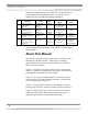
APPENDIX D QUICK CHART FOR THE FILTERED ENCLOSURES Model Size Sash Height from Work Surface (inches) Total Open Area with Bypass (sq. ft.) Exhaust Airflow Volume at 90fpm (CFM) Alarm Airflow Volume at 60 fpm (CFM) Initial Mag. Gauge Pressure Reading (inches H2O) Number of Laskin Nozzles needed at 10 psig Exhaust HEPA Filter w/ Gasket Dimensions (inches) *Motor Horsepower (HP) *Capacitor (MFD, Volts) Fluorescent Lights UV Light on Class I only 2' 9.44 1.45 130 85 0.20 to .045 1 18x18x3.31 0.
APPENDIX E REFERENCES ON VENTILATION, SAFETY, OCCUPATIONAL HAZARDS, BIOSAFETY AND DECONTAMINATION Many excellent reference texts and booklets are currently available. The following is a brief listing: Laboratory Ventilation Standards Federal Register 29 CFR Part 1910 Non-mandatory recommendations from “Prudent Practices.” • Fume hoods should have a continuous monitoring device • Face velocities should be between 60-100 linear feet per minute (lfpm) • Average 2.
Appendix E: References Occupational Health and Safety U.S. Department of Labor 200 Constitution Avenue N.W. Washington, DC 20210 (202) 523-1452 www.osha.gov Industrial Ventilation-ACGIH • Fume hood face velocities between 60-100 lfpm • Maximum of 125 lfpm for radioisotope hoods • Duct velocities of 1000-2000 fpm for vapors, gasses and smoke • Stack discharge height 1.3-2.0 x building height • Well designed fume hood containment loss, <0.10 ppm Industrial Ventilation, A Manual of Recommended Practice.
Appendix E: References American Industrial Hygiene Association 2700 Prosperity Avenue, Suite 250 Fairfax, VA 22031 (703) 849-8888 www.aiha.org SEFA 1-2002 • Fume hood face velocities based on toxicity levels of chemicals Class A – 125 to 150 fpm Class B – 80 to100 fpm Class C – 75-to 80 fpm • Test method – face velocity profile and smoke generation Scientific Equipment & Furniture Association 1028 Duchess Drive McLean, VA 22102 (703) 538-6007 www.sefalabs.
Appendix E: References General References American Conference of Governmental Industrial Hygienists. Industrial Ventilation, A Manual of Recommended Practice, Cincinnati, OH ASHRAE Standard Committee. ASHRAE Standard Atlanta: ASHRAE Publications Sales Department, 1995 British Standards Institution, Laboratory Fume Cupboards.
Appendix E: References Kruse, R.H., WH. Puckett and J. H. Richardson. 1991. Biological Safety Cabinetry, Clin. Microbiol. Rev. 4:207241. Miller, C.D., D.H.M. Groschel, J. H. Richardson, D. Vesley, J. R. Songer, R. D. Housewright and W. E. Barkley. 1986. Laboratory Safety, Principles and Practices, American Society for Microbiology, Washington, D.D. National Research Council (U.S.) Committee on Hazardous Biological Substances in the Laboratory. 1989. Biosafety in the Laboratory.
87
For more information, please contact us: ExpotechUSA 10700 Rockley Road Houston, Texas 77099 USA 281-496-0900 [voice] 281-496-0400 [fax] E-mail: sales@expotechusa.com Website: www.ExpotechUSA.