GD-P1000E1000 TP/MM GeoDesy Kft. H-1116 Budapest, Kondorfa str. 6-8. Telefon: 06-1-481-2050 Fax.: 06-1-481 -2049 E-mail: info@geodesy.hu http://www.geodesy.
Table of contants 1 Introduction....................................................................................................................... 4 1.1 What is FSO?............................................................................................................... 4 Why is it important? .................................................................................................... 4 1.3 Optical Free-space Transmission ..............................................................
10.1.3 Status info screen ............................................................................................... 26 10.1.4 Device setup ....................................................................................................... 27 10.1.5 IP Setup .............................................................................................................. 28 10.1.6 SNMP Setup ......................................................................................................
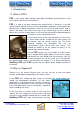
1 Introduction 1.1 What is FSO? FSO is free space optics provides point-point broadband communications using Laser Light as the transmission medium. FSO is a state of art data communication method which is based on a very old communication solution. Ancient Chinese developed a protection system against the Mongol tribes, building watchtowers within the line of site to other towers.
very hard receiver sensitivity. These two factors combined to provide one of the best performing FSO systems on the market today. To meet the demands for every higher bandwidth, GeoDesy FSO (Europe) Limited continues to invest heavily in research and development with the newest product line which offers Gigabit speeds being launched. This manual describes the GeoDesy FSO Next series of free space laser transmission system.
1.3 Optical Free-space Transmission The principle used in free space laser transmission is very similar to the one is used for fibre optic transmission. The difference is while fibre optic devices use electronics and optics optimized for transmission to the air. Also one can observe to the similarity in the transmission properties. No galvanic contact, no ground-loops, no need for surge protection, noise immunity, long distances, high bandwidth.
1.4 Typical applications Most typically the GeoDesy FSO Next product are is used to interconnect LANs. The system is protocol transparent, thus other applications also can be taken into consideration. Appropriate interface converters are needed and system bandwidth must be matched for that. Here we collected some circumstances, where the deployment of the GeoDesy FSO is the most adequate as a cost effective solution.
2 Interfaces for the Giga Next Series 2.1 1000Mbps TP interface The GeoDesy FSO Giga Next series products are designed to provide easy-touse and cost-effective solution for interconnecting Local Area Networks. By utilizing standard Category 5e cable and using standard IEEE802.3af interface the deployment of the system is easier than ever before. The transparent and wire speed data transfer together with virtually zero latency assures the easy integration of the system in all environments.
3 Sites of installation 3.1 Key factors of operation There are four key issues that the site survey has to shed light on. Proper system operation cannot be guaranteed without satisfying all of the four requirements. Clear line of sight - The entire optical path between the two ends must be free of any obstacles. It not only means that one has to see the other side, but other possible sources of disturbance should also be taken into consideration.
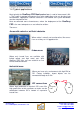
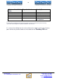
Preferred installation Pay attention to sites Avoid (*) Concrete wall Brick wall Soft materials Chimneys Wooden constructs Metal masts or Frames Hidden heat isolations, like Styrofoam Behind window Old constructs Microwave towers (*) In cases where installations are listed under “AVOID” cannot be avoided than special mounting accessories to be designed and special installations must be used. It is not only the building that has to be solid, but the support structure too.
3.3 Distance measurement Because the units were designed, and calibrated for certain distance operations the higher distance will decrease the availability. GeoDesy FSO pre-calibrates and pretests every unit shipped to the customer. To ensure that the unit you are about to buy fits to the needs, the first step is to measure the distance. The best way to measure it is by GPS (Global Positioning System), these units are accurate enough to determine the distance between two points.
4 Eye safety There are no two installation spots of the same kind, the buildings or structures, the available space and the accessibility of the place will be different in each case. Nevertheless, as a general rule it is very important to select the installation site so that nobody can look directly into the transmitter.
5 The mounting bracket In the following chapter you will find detailed description of the bracket fastenings. 5.1 Mounting brackets for the X Series GeoDesy FSO provides the mounting bracket and all the necessary components for X series units.
2pcs M6x90 bolt Head fixing 3pcs M6x25 screw Head fixing 3pcs M6 bolt head fixing 6pcs 6mm spacer bracket and head fixing 6pcs 6mm spring spacer bracket and head fixing Mounting Hole Patterns GeoDesy Kft. H-1116 Budapest, Kondorfa str. 6-8. Telefon: 06-1-481-2050 Fax.: 06-1-481 -2049 E-mail: info@geodesy.hu http://www.geodesy.
6 System connection Important: Please only solder UV proof 3 wire cooper cable into its place as in below photos. before soldering after soldering 6.1 Power Adapter GeoDesy Kft. H-1116 Budapest, Kondorfa str. 6-8. Telefon: 06-1-481-2050 Fax.: 06-1-481 -2049 E-mail: info@geodesy.hu http://www.geodesy.
7 System installation 7.1 On the table test Warning! Do not look either into the transmitter or the receiver optics because at this distance even the reflected laser beam can be dangerous to your eyes. Operating the system on much shorter distance than presumed originally can cause saturation or even permanent damage to the receiver. Always use optical attenuators for this kind of test. The on-the-table test needs careful planning and careful use during the test period.
7.1.1 Alignment of the PX1000E1000 The first step after the unit was placed to the bracket, and the units facing each other. On the back of the receiver you can find the LEDs and LCD screen for the local received level and the remote received level. This help will be very useful because as soon as you have received – which is very easy to achieve – you can see the effect of your local sides movement to the other side. For further information please check the Meanings of the LCDs chapter. 7.
7.3 System layout 7.3.1 Connecting to your Network The system is connected to the network via two twisted pair cable and one wire cooper cable. The first cable provides the management data for the GeoDesy FSO Giga Next laser head The second plug houses the Gigabit TP or the Fibre optic connection point.Please see the connection below.This is the standard IEEE802.3af connector layout. GeoDesy Kft. H-1116 Budapest, Kondorfa str. 6-8. Telefon: 06-1-481-2050 Fax.: 06-1-481 -2049 E-mail: info@geodesy.
8 The mounting bracket 8.1 Fixing the heads Your GD-P1000E1000 head can be fixed to its stand with an Alignment Base Unit (ABU). On the figure you can see an ABU, and a plinth of a GD1000E1000 unit, and the necessary fixing parts. The necessary nuts and washers can be foubd on the legs of the head. The steps of the fixing are. First, fix the Abu to the stand using the washers and nuts Place the head to the ABU Fix the bolts with the nuts, using the washers Tight up all the nuts 8.
Place the two spacers where the figure shows to. Open the spacers until it reaches the bottom of the upper plate of the ABU! Repeat this on the back side too! Then do the same on the remote side too! 8.3 Inside the laserhead Warning only trained personal should open the casing. No user servicable part inside. GeoDesy Kft. H-1116 Budapest, Kondorfa str. 6-8. Telefon: 06-1-481-2050 Fax.: 06-1-481 -2049 E-mail: info@geodesy.hu http://www.geodesy.
9 Alignment The very first step is to power up the heads. After this the boot sequence should run down, which takes 10-15 seconds. 9.1 LCD panel (receiver) Aligment Important! For alignment purposes you might need a computer connected to the system. The adjustment of the motor control, and the swithcing of the transmitters are possible with a PC. For adjustment please see PX-1000E1000 extra MGM functions chapter.
On the LCD screen you can see the remote level of the other Laser Head! Because of the weight of the heads for the vertical moving you can use the spacers as it is shown on the figure. For this moving you need two wrencches.
You can check the position of the beam using a digital camera with infared lenses. You can see the beam shining on the landmarks around the remote head from the side of the transmitter, or until dusk you can see the line of the beam with your own eyes.
there you can measure it. In that case if there are not any surfaces for beam measuring, you can do it in the following method: Face the remote side and check the beam with your camera. Move slowly to the right in straight line until the picture of the beam, what you see in the camera, is reducing, and sign that place. Do the same on the left side. Then you can measure the distance between the twosigned places. That will be the diameter of the beam.
10 Management 10.1 Features The Inband network-monitoring unit is a newly developed highly featured monitoring for GeoDesy FSO manufactured laser links. This high quality equipment allows the user to monitor the link statuses such as detector voltage transmitter status, and many other features of the Laser link. Nevertheless, this chapter is intended to describe the usage of this network monitoring, and its connection and relationship with the GeoDesy FSO laserheads.
10.1.3 Status info screen Clicking on the Device Setup you will enter the main status information screen, which will give you good summarized information of the device, s uch as status information of the transmitters, detector level, or temperature values. Laser ON: Transmitter transmitts Laser OK: Transmitter works properly, transmitts and the transmitted signal is valid. Temperature: ambient temperature inside the device.
10.1.4 Device setup The device setup screen leads you to the main monitoring options. Here the alarms can be set and main information about the Laser head. Device name: uniqe identifier of the device Managed head: Type of the laserhead Detector alert level: when the received level reach this value, the alarm will be triggered. Temperature alert level: when the temperature reach this value, the alarm will be triggered.
10.1.5 IP Setup Clicking on the IP Setup link you can have access to the Ethernet module of the system, this will make easy access to the IP number and/or port settings. These settings are sensitive setting and some of them cannot be restored by the use r. Please always do the changes with extra care! If you have doubt in any step, do not hesitate to contact the technical support of the manufacturer website for further information. Local IP: the IP address of the local device can be set in this box.
10.1.6 SNMP Setup One of the main features of the device is the SNMP(Simple Network Monitoring Protocol). The SNMP settings can be set on this page. Trap address: The IP address of the SNMP trap over the network. Trap events in the system you have possibility to setup three different trap event. For further details on the trap event see Trap event list chapter of this book. In this section there are the settings of the SNMP Agent.
10.1.7 Security On the security section you can set the username and the password for the unit. If you have forget the usernam and/or the password please contact The technical support. MGM Trusted-host filtering: Here you can adjust two adresses where you can till in from which computer with you reach teh MGM! To adjust you will hove to adjust a filter. Filter adjust: Off:Turned off. IP:Only see the IP address. MAC: Only see the MAC address.
10.2 Additional functions(PX-P1000E1000 extra MGM features) Additional functions Transmitter on and off: you can switch the transmitters on and off individually. ACM: (aperture control mechanism) Default: auto mode, the system will automatically regulate the incoming light to the optimal level of Udet, preventing the system to get oversaturated. Manual: The incoming light can be regulated manually; the use of the manual mode is strongly suggested during installation.
10.3 Mandatory Management Activation Thank you for buying our product. Please read this note carefully. From software version (3.2.1218/R090x)! The product you have bought has fully functional management software, which has limitation only in time. The unit activation request should be sent to activation@geodesy-fso.com. And the activation code will be issued, later and sent to the email address give, or can be accessed from your local distributor.
10.4 Firmware update The firmware update has the following steps: Run FTP client Log-in to the Laser-head Copy Geodesy_FWUpdate_Vxx.xbn over Log in the laserhead Click on update Wait 50-60 seconds Restart the laserhead Run FTP client FTP client setup IP address: the IP address of the device (192.168.100.220 or 192.168.100.221 as a factory default ) or the IP address you gave to the system earlier – same as the IP address for the Web management.
Log off the FTP server Now the Update button will be active Click on update and the update process will start it takes upto 60 seconds. The LEDs on the back of the device will go off than lit one after the other. Make sure that the system power is fixed and the power will not go off during the update process. If the LEDs froze, wait 2-3 minutes before unplugging the power cable, and repluging again. 10.
11 Setting up the SNMP Please check the GD view manual for details how to proceed to this point 1. Figure On Figure 1 you can see our test setting. The GD-View is sending 3 traps LaserHeadAlarm (OID: 1.3.6.1.4.1.17857.0.1201) This trap will be sent after any of the alarms will go on (for alarm setting please see chapter 5.4) LaserHeadAlarmCancel (OID: 1.3.6.1.4.1.17857.0.1202) After the alarm goes off this trap will be sent DeviceDown (OID: 1.3.6.1.4.1.17857.0.
11.1.1 SNMPc Installation First run snmpc600eval.exe file from the CD. Run through the setup process by clicking next GeoDesy Kft. H-1116 Budapest, Kondorfa str. 6-8. Telefon: 06-1-481-2050 Fax.: 06-1-481 -2049 E-mail: info@geodesy.hu http://www.geodesy.
When the setup asks for the discovery seed enter you own IP address, Subnet mask a community After the setup was finished hit OK. Your PC might ask for a restart, in that cases please restart your PC SNMPC 11.1.2 Configuration of the SNMPc Management console GeoDesy Kft. H-1116 Budapest, Kondorfa str. 6-8. Telefon: 06-1-481-2050 Fax.: 06-1-481 -2049 E-mail: info@geodesy.hu http://www.geodesy.
Click on Start => Programs => SNMPc network manager => Startup system. This will start the SNMPc Management console. Can be seen on Figure 3 3. Figure To add the GD-View to the console click on Insert => Map Object => Device. As it is shown on Figure 4 4. Figure GeoDesy Kft. H-1116 Budapest, Kondorfa str. 6-8. Telefon: 06-1-481-2050 Fax.: 06-1-481 -2049 E-mail: info@geodesy.hu http://www.geodesy.
After the Map Onject was added, the properties should be set: Label : GeoDesy-FSO MGM (cannot contain spaces, or special caracters) see Figure On the Access Tab Read Access Mode: SNMPV1 Read/Write Access Mode: SNMPV1 Read community: public Read/Write Community: public Trap community: public The rest of the setting can be left on factory default. GeoDesy Kft. H-1116 Budapest, Kondorfa str. 6-8. Telefon: 06-1-481-2050 Fax.: 06-1-481 -2049 E-mail: info@geodesy.hu http://www.geodesy.
11.1.3 Compiling GeoDesy-FSO Mib file First copy the Mib file (GeoDesy-FSO.mib [Source: CD:\Mib\V07\GeoDesyFSO.mib]). Copy this file over to : C:\Program Files\SNMPc Network Manager\mibfiles\ To Compile the MIB file to the SNMPc Click on Config=>Mib Database After opening the Mib Database, you should add the MIB file to the Database: Click on Add. Add Mib files: find GeoDesy-FSO.mib, then click OK GeoDesy Kft. H-1116 Budapest, Kondorfa str. 6-8. Telefon: 06-1-481-2050 Fax.
After you hit OK you have added the Mib file to the database now you will have to compile it to the management console. So find again GeoDesy-FSO.mib and highlight it. Than Hit compile. It will ask you whether you want to compile it click on Yes. GeoDesy Kft. H-1116 Budapest, Kondorfa str. 6-8. Telefon: 06-1-481-2050 Fax.: 06-1-481 -2049 E-mail: info@geodesy.hu http://www.geodesy.
11.1.4 Using SNMP to monitor the link First click on the GeoDesy-FSO Object to highlight it. Open mgmt/system/SystemInfo right click on the object and view Table This table will show you the main System information Table: To see the head entries open: private/GeoDesy-FSO/headData GeoDesy Kft. H-1116 Budapest, Kondorfa str. 6-8. Telefon: 06-1-481-2050 Fax.: 06-1-481 -2049 E-mail: info@geodesy.hu http://www.geodesy.
Right click on the head entry table and view table. Now the SNMP is completely set up. GeoDesy Kft. H-1116 Budapest, Kondorfa str. 6-8. Telefon: 06-1-481-2050 Fax.: 06-1-481 -2049 E-mail: info@geodesy.hu http://www.geodesy.
11.1.5 Generating failure While the SNMP is working, if you would like to see that actually, it really does what it suppose to be, unplug the RJ11 (RS485) cable from the GD-View. After a few seconds the trap message should arrive to your PC. After reconnecting the RS485 cable the trap message should arrive that the alarm was canceled GeoDesy Kft. H-1116 Budapest, Kondorfa str. 6-8. Telefon: 06-1-481-2050 Fax.: 06-1-481 -2049 E-mail: info@geodesy.hu http://www.geodesy.
You can acknowledge the alarm with a right click on the alarm. GeoDesy Kft. H-1116 Budapest, Kondorfa str. 6-8. Telefon: 06-1-481-2050 Fax.: 06-1-481 -2049 E-mail: info@geodesy.hu http://www.geodesy.
11.1.6 SNMP Technology SNMP is part of the Internet network management architecture. This architecture is based on the interaction of many entities, as described in the following section. The Internet Management Model As specified in Internet RFCs and other documents, a network management system comprises: Network elements -- Sometimes called managed devices, network elements are hardware devices such as computers, routers, and terminal servers that are connected to networks.
parties. An SNMPv2 entity can define multiple parties, each with different parameters. For example, different parties can use different authentication and/or privacy protocols. Management protocol -- A management protocol is used to convey management information between agents and NMSs. SNMP is the Internet community's de facto standard management protocol. The most basic elements of the Internet management model are graphically represented in Figure 1.
A MIB can be depicted as an abstract tree with an unnamed root. Individual data items make up the leaves of the tree. Object identifiers (IDs) uniquely identify or name MIB objects in the tree. Object IDs are like telephone numbers -- they are organized hierarchically with specific digits assigned by different organizations.
Gauges -- Non-negative integers that can increase or decrease, but latch at a maximum value. The length of an output packet queue (in packets) is an example of a gauge. Time ticks -- Hundredths of a second since an event. The time since an interface entered its current state is an example of a tick. Opaque -- Represents an arbitrary encoding. This data type is used to pass arbitrary information strings that do not conform to the strict data typing used b y the SMI.
GetBulk -- New for SNMPv2. The GetBulk operation was added to make it easier to acquire large amounts of related information without initiating repeated get-next operations. GetBulk was designed to virtually eliminate the need for GetNext operations. Set -- Allows the NMS to set values for object instances within an agent. Trap -- Used by the agent to asynchronously Inform the NMS of some event. The SNMPv2 trap message is designed to replace the SNMPv1 trap message. Inform -- New for SNMPv2.
Error-status -- Indicates an error and an error type. In SNMPv2 GetBulk operations, this field becomes a NonRepeaters field. For these operations, this field defines t he number of request-ed variables listed that should be retrieved no more than once from the beginning of the request. The field is used when some of the variables are scalar objects with only one variable. Error-index -- Associates the error with a particular object instance.
The Digest Authentication Protocol verifies that the message received is the same one that was sent. Data integrity is protected using a 128-bit message digest calculated according to the Message Digest 5 (MD5) algorithm. The digest is calculated at the sender and enclosed with the SNMPv2 message. The receiver verifies the digest. A secret value, known only to the sender and the receiver, is prefixed to the message.
Trap event list Alert disabled: there is no alert coming up for this trap Temperature: The agent will send an alarm if the value goes above the preset value. For further details please see Temperature alert level in the Device Setup chapter. Detector: The agent will send an alarm if the value goes above the preset value. For further details please see Detector alert level in the Device Setup chapter. Transmitter: if the transmitter fails operating the agent will send an alarm.
12 Warranty conditions GeoDesy FSO (Europe) LTD warrants that the GeoDesy FSO product purchased will free from defects in material and workmanship for a period of one (1) year from the date of purchase. This warranty period will not be extended by virtue of a repair of the product or a replacement of any component of the product during the warranty period. This warranty covers only normal commercial use.
product was defective within the terms of the warranty; otherwise the purchaser or user shall be responsible for costs of return handling and transportation. If the GeoDesy FSO product does not operate as warranted above, the customer’s sole remedy shall be repair or replacement.